










A sapphire wafer can meet an average thickness target and still be expensive to finish. The problem may be a systematic shape deviation that follows crystal orientation rather than a random machine error. Because sapphire is anisotropic, its elastic and fracture response changes with crystallographic plane and cutting direction. The diamond wire can therefore experience an unequal lateral response even when speed, feed and commanded tension are unchanged.
A 2026 study made this production issue unusually concrete. Under the researchers’ conditions, 4-inch R-plane sapphire showed shape deviation up to 114.1 micrometers, compared with 20.6 micrometers for C-plane material. A variable-feed strategy reduced the R-plane deviation by about 15% without reducing cutting efficiency. Those values are study-specific, not universal specifications. Their practical meaning is broader: orientation belongs in the sapphire wafer cutting recipe and traceability record.
This article explains how anisotropy becomes wire deflection, how to separate it from thermal warp or TTV, and how to qualify a diamond wire saw for sapphire substrates and optical components.
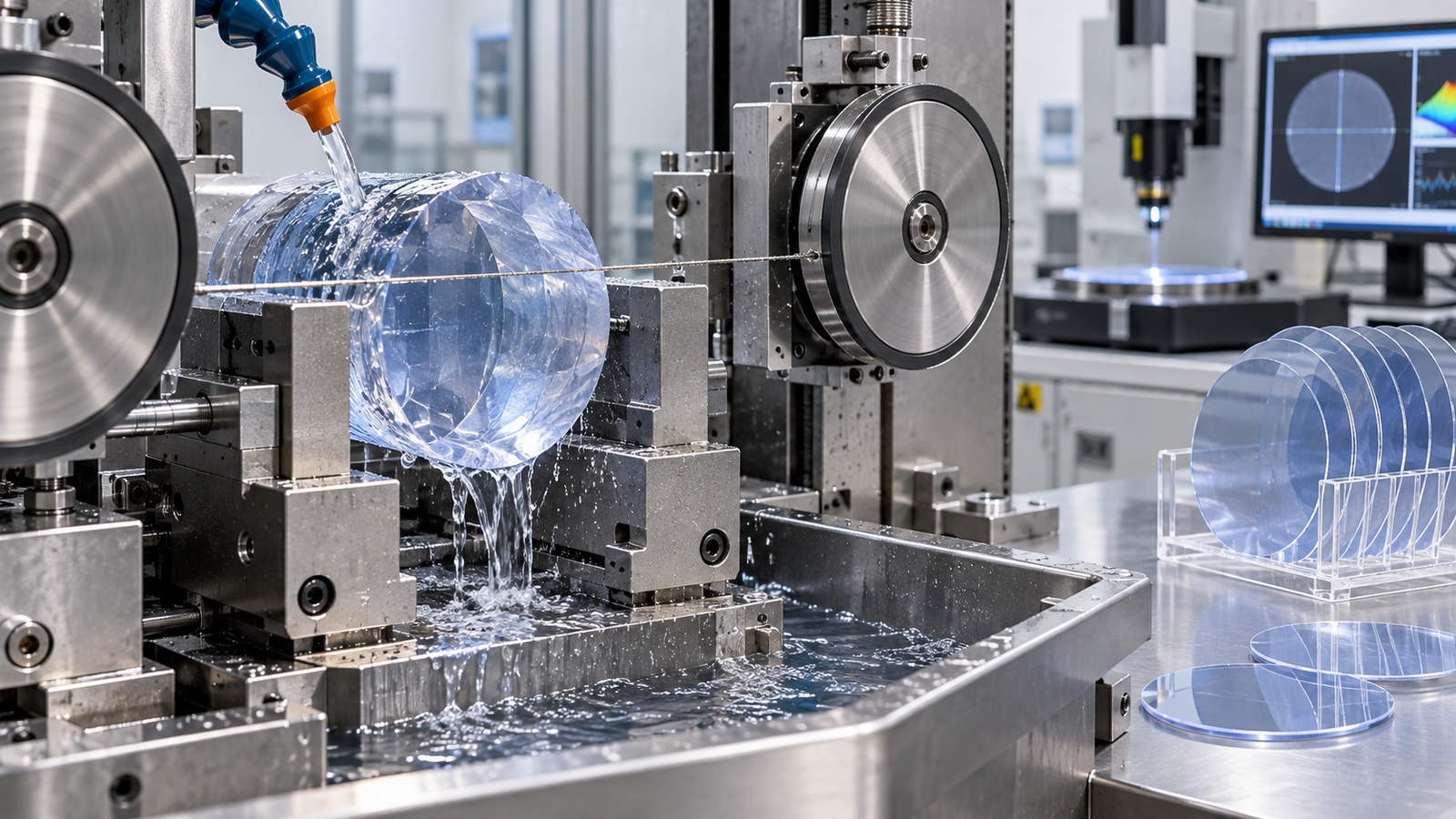
Why sapphire is not the same material in every direction
Sapphire is single-crystal aluminum oxide. Its hardness, optical performance and thermal stability suit LED and RF substrates, optical components and infrared windows, while making it costly to machine. Removal combines scratching, ploughing, microfracture and occasional ductile-mode deformation at small grain penetration depths.
C-plane, A-plane, M-plane and R-plane define the finished surface relative to the lattice. Abrasive response changes with that orientation and feed direction. A 2024 study reported lower sawing capability for A-plane than C-plane sapphire under its conditions; the 2026 shape-deviation study found especially strong asymmetry for R-plane slicing.
This is why a recipe copied from one plane may fail on another. Even two R-plane trials can differ when the in-plane feed angle, wire condition, boule orientation accuracy or fixture datum changes. A purchase order that says only “sapphire” leaves out process-critical information.
How anisotropy turns into wafer shape deviation
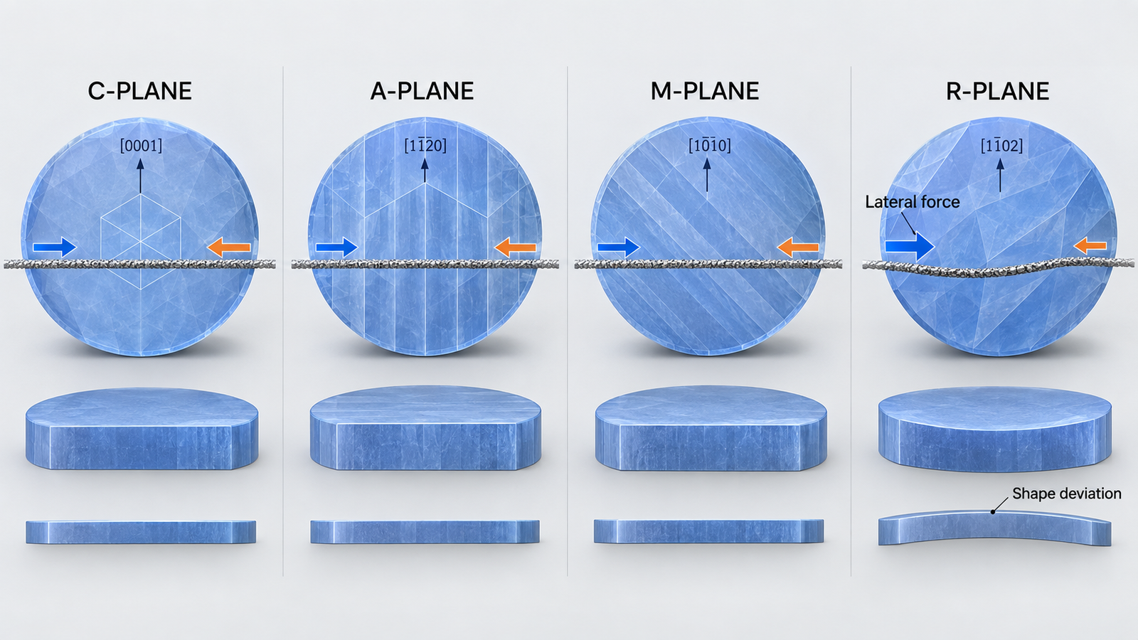
During cutting, feed force pushes the flexible wire into a bowed path. Tension, guide spacing and wire stiffness resist the bow. In an isotropic approximation, forces on the two sides of the wire are treated as balanced. In anisotropic sapphire, the effective elastic and fracture response can be different on either side of the wire for a given orientation and feed angle.
That imbalance creates a lateral force. The wire shifts from the intended plane, and the shift changes with contact arc and material engagement. The resulting gradual shape error may be much larger than local roughness.
The mechanism is important because polishing removes local peaks but does not cheaply correct every bulk geometry error. Correcting a curved or laterally deviated slice consumes thickness, process time and material. If the required removal approaches the available finishing allowance, the wafer becomes scrap even when the cut surface initially looks smooth.
Do not confuse shape deviation, TTV, warp and roughness
Many supplier trials fail at the language stage. The customer asks for flatness, the equipment supplier reports roughness, and neither side has defined the wafer support condition. Use separate terms and measurement methods.
| Metric | What it describes | What it can indicate |
|---|---|---|
| Surface roughness | Short-wavelength texture and saw marks | Abrasive engagement, grain size, debris recutting |
| Waviness or profile error | Longer-spatial-wavelength surface variation | Wire vibration, bow evolution, feed modulation |
| TTV | Difference between maximum and minimum wafer thickness | Relative front/back geometry and path consistency |
| Bow | Center displacement from a reference plane in a free wafer | Stress and global shape asymmetry |
| Warp | Overall deviation of the median surface | Complex global distortion |
| Shape deviation | Departure of the cut surface from its intended plane or profile | Lateral wire deflection, anisotropy, fixture or thermal effects |
Use a non-contact full-surface map where possible, retain the orientation mark in the data file, and report profiles parallel and perpendicular to the wire direction. A single center-thickness reading cannot find an anisotropy-driven pattern.
Separate anisotropy from other causes of poor sapphire geometry
Check orientation and feed angle first
If the error rotates with the crystal while the setup remains fixed, suspect orientation. If it remains in machine coordinates, inspect alignment, guides, fixture compliance and thermal gradients. Deliberately change crystal or feed direction while controlling wire lot, wear state and coolant.
Look at the error through cutting time
Mark entry, maximum-contact and exit locations on the profile. An error that grows with contact length may indicate increasing bow or inadequate debris removal. A repeating pitch may point to motion, wheel or wire phenomena. A slow one-direction drift can reflect lateral force, fixture movement or thermal expansion.
Inspect the wire and coolant evidence
A worn wire raises force and bow, which can amplify an orientation-sensitive response. Clogged coolant paths can create local heat and debris recutting. Before changing the orientation recipe, confirm abrasive condition, actual fluid delivery and filter loading. The goal is to avoid using feed compensation to mask a maintenance problem.
Control levers for sapphire cutting with a diamond wire saw
Feed direction
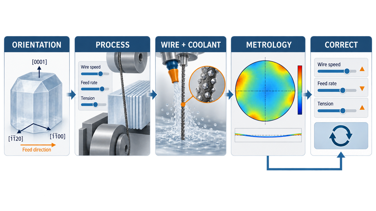
For anisotropic planes, in-plane direction should be treated as a controlled factor. Run a small orientation screen rather than assuming that the shortest fixture setup is best. Record the crystal datum, mounted rotation and wire travel direction in degrees. If a favorable symmetry direction is found, convert it into a fixture key or digital setup check so it survives operator changes.
Variable feed
Constant feed does not keep load constant as contact length changes. A variable profile can slow near maximum contact or strong lateral response, then recover time elsewhere. The 2026 R-plane study reported about 15% less shape deviation with its strategy. Treat that as evidence to test, not a guaranteed result.
Wire speed and tension
Higher wire speed increases abrasive engagements and can improve chip transport, but it also increases sliding distance. Higher tension reduces deflection, but excessive tension raises wire, guide and breakage risk. Tune speed, feed and tension as a system. Monitor actual tension response or wire bow where available; a setpoint does not show what happens inside the cut.
Diamond wire specification
Wire diameter, abrasive size, protrusion, density and bond retention influence kerf, force, finish and life. Finer wire can reduce geometric loss; more aggressive abrasive can increase removal capacity. Qualify at a defined wear state because new and blunted wire may produce different lateral forces. The diamond wire selection guide compares specifications.
Coolant delivery
Coolant must reach the active contact, remove heat and carry alumina debris away without destabilizing the wire. Record nozzle location, fluid concentration, temperature, flow and filter differential pressure. A 2024 thermal model of sapphire wire sawing linked process inputs to wafer temperature and warpage, reinforcing the need to treat cooling as a geometric control variable rather than housekeeping.
A practical sapphire anisotropy qualification plan
- Define the material. Record crystal plane, off-angle if applicable, boule dimensions, supplier lot, orientation mark and cut direction.
- Choose a metrology map. Measure thickness and surface profile at fixed coordinates tied to the crystal and wire directions. Define support and filtering conditions.
- Stabilize non-material variables. Use a controlled wire-conditioning window, verified alignment, documented fixture and fresh or characterized coolant.
- Screen feed angles. Compare a small set of physically meaningful directions while holding speed, average feed and tension constant.
- Map contact stages. Correlate entry, center and exit geometry with drive load, bow or force proxy, tension response and coolant state.
- Test variable feed. Change the profile only after the baseline mechanism is visible. Evaluate shape, cycle time, roughness and chipping together.
- Repeat across wire life. Confirm that the selected direction and profile remain stable after abrasive wear develops.
- Validate finishing cost. Grind or lap representative wafers and measure how much stock was required to meet the final geometry.
Use enough repeats to distinguish a directional effect from ordinary run-to-run noise. Preserve raw maps and time-series machine signals. Averaging all wafers into one number can erase the exact spatial pattern needed for diagnosis.
Endless diamond wire saw versus diamond multi-wire saw for sapphire
An endless diamond wire saw is well suited to orientation screening, R&D, special-shape blanks, optical components and low-volume precision cuts. The closed loop repeatedly presents the same wire to the workpiece, which helps engineers study wire behavior and inspect a defined abrasive population. It is a practical platform for determining whether feed direction or variable feed improves the target part.
A diamond multi-wire saw is appropriate when many parallel sapphire wafers or plates must be produced per cycle. It adds wire-web variables: pitch, groove accuracy, tension distribution, coolant access and wafer position. A direction that works on one wire still needs confirmation across the web. For high-volume procurement, require lane-to-lane geometry data and preserve each wafer’s position.
A desktop endless loop diamond wire saw can support coupons and laboratory studies, but it does not directly prove full-boule production capability. Use it to identify mechanisms and narrow trials.
What purchasing teams should put in the RFQ
- Sapphire plane, orientation tolerance, in-plane datum and material lot information
- Blank dimensions, target slice thickness, finishing allowance and usable edge zone
- TTV, bow, warp, profile, roughness, chipping and crack acceptance limits
- Metrology instrument, support condition, spatial filter and sampling map
- Required throughput, batch size, wire-life target and changeover method
- Coolant chemistry restrictions, filtration, cleanliness and contamination limits
- Data-export needs for tension, load, speed, feed, alarms and wafer traceability
- Factory acceptance material and the number of repeated qualification cuts
Ask suppliers to report both the best result and the distribution. If shape error depends on orientation, a single display wafer says little about production risk.
How ewirexon supports sapphire and optical substrate cutting
Ewirexon supplies endless diamond wire saw, diamond multi-wire saw and desktop endless-loop platforms for hard and brittle materials. Its application scope includes sapphire substrate cutting, precision optical wafer processing, quartz, optical glass, ceramics and compound-semiconductor materials.
For an orientation-sensitive sapphire project, the useful contribution is not a universal parameter table. It is a trial plan that connects crystal datum, fixture, wire specification, speed-feed-tension history, coolant delivery and full-surface metrology. Ewirexon’s process consulting and customized equipment development can be evaluated against those inputs for laboratory, pilot or production needs.
Conclusion
Sapphire wafer cutting is governed by both machine mechanics and crystal mechanics. When anisotropy creates an unbalanced lateral response, the diamond wire can leave the intended plane even though nominal settings remain stable. The cost appears later as extra grinding, lost thickness, poor final shape or rejected wafers.
A precision diamond wire saw offers narrow-kerf, low-force cutting, but the process must still be oriented, measured and controlled. Start with the exact crystal plane and feed direction, map the full surface, correlate shape to cutting time, and test variable feed only after other causes are stabilized. Those steps turn a material-science observation into a procurement specification and a repeatable production method.
Frequently asked questions
Why does sapphire crystal orientation affect diamond wire saw cutting?
Sapphire’s elastic, fracture and deformation behavior varies by crystal plane and direction. This can create unequal forces around the wire, changing cutting force, bow and lateral path even when machine setpoints are unchanged.
Which sapphire plane is hardest to cut?
There is no single ranking for every outcome and process. Published studies have reported lower sawing capability for A-plane than C-plane and much larger shape deviation for R-plane under specific conditions. The relevant plane and in-plane direction must be tested on the target machine.
Can higher diamond wire tension eliminate sapphire shape deviation?
Higher tension can reduce bow, but it does not remove crystal anisotropy and may increase wire or guide risk. Tension should be optimized with feed, speed, wire specification, fixture and cooling rather than raised alone.
How does variable feed improve sapphire wafer cutting?
Variable feed can lower load where contact length or lateral response is greatest and recover cycle time in easier zones. It should be qualified against shape, roughness, chipping and cycle time; it is not automatically beneficial for every orientation.
Should I choose an endless diamond wire saw or diamond multi-wire saw?
Choose an endless diamond wire saw for R&D, orientation trials, special parts and small batches. Choose a diamond multi-wire saw when parallel-wafer throughput is required, then qualify lane-to-lane pitch, tension, cooling and geometry consistency.
Technical references
- Material anisotropy-induced shape deviation of sliced sapphire wafers and its suppression in wire sawing.
- Analysis of Wafer Warpage in Diamond Wire Saw Slicing Sapphire Crystal.
- Wire Bow In Situ Measurement for Monitoring the Evolution of Sawing Capability during Slicing Sapphire.
- A study on the evolution of sawing force and bow angle in diamond wire sawing of sapphire.
Editorial note: Numerical results are attributed to the cited experiments and should not be treated as universal machine specifications. The figures are AI-generated engineering illustrations; they do not represent customer installations, certified crystal drawings or measured production data.