
A silicon carbide boule is not an isotropic cylinder. The crystallographic plane selected for the wafer, the direction of the intentional off-axis angle and the wire travel direction all influence how cracks initiate, how cutting force develops and where waviness appears. That matters especially for 4H-SiC substrates specified with a nominal 4° off-axis orientation, a common starting surface for epitaxial growth.
For a production team, orientation is more than a certificate field. If boule mounting rotates between lots, an apparently unchanged diamond wire saw recipe can produce different entry chips, wire bow, total thickness variation (TTV) and finishing allowance. The resulting drift is often blamed on wire quality or machine stiffness when the real cause is an uncontrolled relationship between crystal coordinates and the cutting path.
This guide explains why 4° off-axis SiC wafer slicing needs orientation-aware process development, which measurements reveal the mechanism, and how engineers can qualify a stable recipe without treating every damaged wafer as a separate mystery.
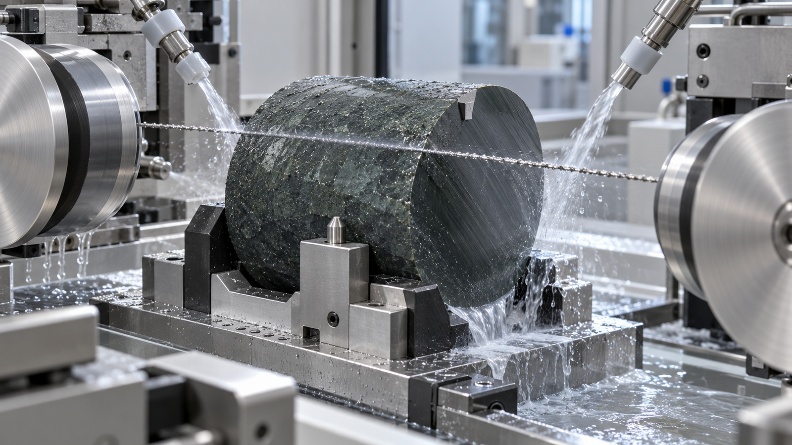
Why 4° off-axis 4H-SiC is used
4H-SiC combines a wide bandgap, high breakdown field and high thermal conductivity. Those properties support efficient high-voltage power devices used in electric vehicles, industrial drives, renewable-energy conversion and data-center power systems. The substrate is commonly cut a few degrees away from the basal plane so subsequent epitaxial growth can proceed by controlled step flow. The exact direction, tolerance and device requirement belong on the substrate specification.
The off-axis geometry has a direct manufacturing consequence. A nominal wafer surface is no longer coincident with a principal crystal plane. Around the boule, the cutting front can meet crystallographic directions with different fracture response. Recent work on 4° off-axis 4H-SiC continues to report orientation-dependent optical and mechanical behavior, including in alternative slicing studies. Diamond wire sawing remains an important industrial reference process, so orientation effects cannot be left only to the crystal-growth or epitaxy teams.
Incoming documentation should therefore include the polytype, growth direction, off-axis angle and direction, major flat or notch convention, resistivity class, usable diameter, edge exclusion and known defect map. A label that says only “SiC boule” is not enough to reproduce a cut.
Why SiC wafer cutting reacts to orientation
SiC is both hard and brittle. Diamond grains remove material through a mixture of microcutting, ploughing and controlled brittle fracture. The local result depends on abrasive protrusion, grain load, coolant access and material response. In a crystal, cleavage tendency, elastic properties and crack propagation are direction dependent. Changing the relation between wire motion and the off-axis vector can therefore change cutting force and damage even when wire speed and feed remain constant.
Four mechanisms deserve attention:
- Directional fracture. Microcracks do not grow equally in every crystallographic direction, so chip shape and subsurface-damage depth can vary around the wafer.
- Changing effective cutting front. Boule geometry and feed direction change contact length during the cycle; the off-axis orientation adds a second directional variable.
- Wire deflection. If removal resistance rises, the wire bows before the feed system reaches equilibrium. The delayed recovery can become thickness error or surface waviness.
- Asymmetric edge support. Entry and exit edges may not respond alike when the off-axis direction is reversed relative to wire travel.
These effects do not mean one orientation is universally “easy” and another “hard.” Machine architecture, wire construction and support method alter the outcome. The practical requirement is to lock the coordinate system and measure the response.
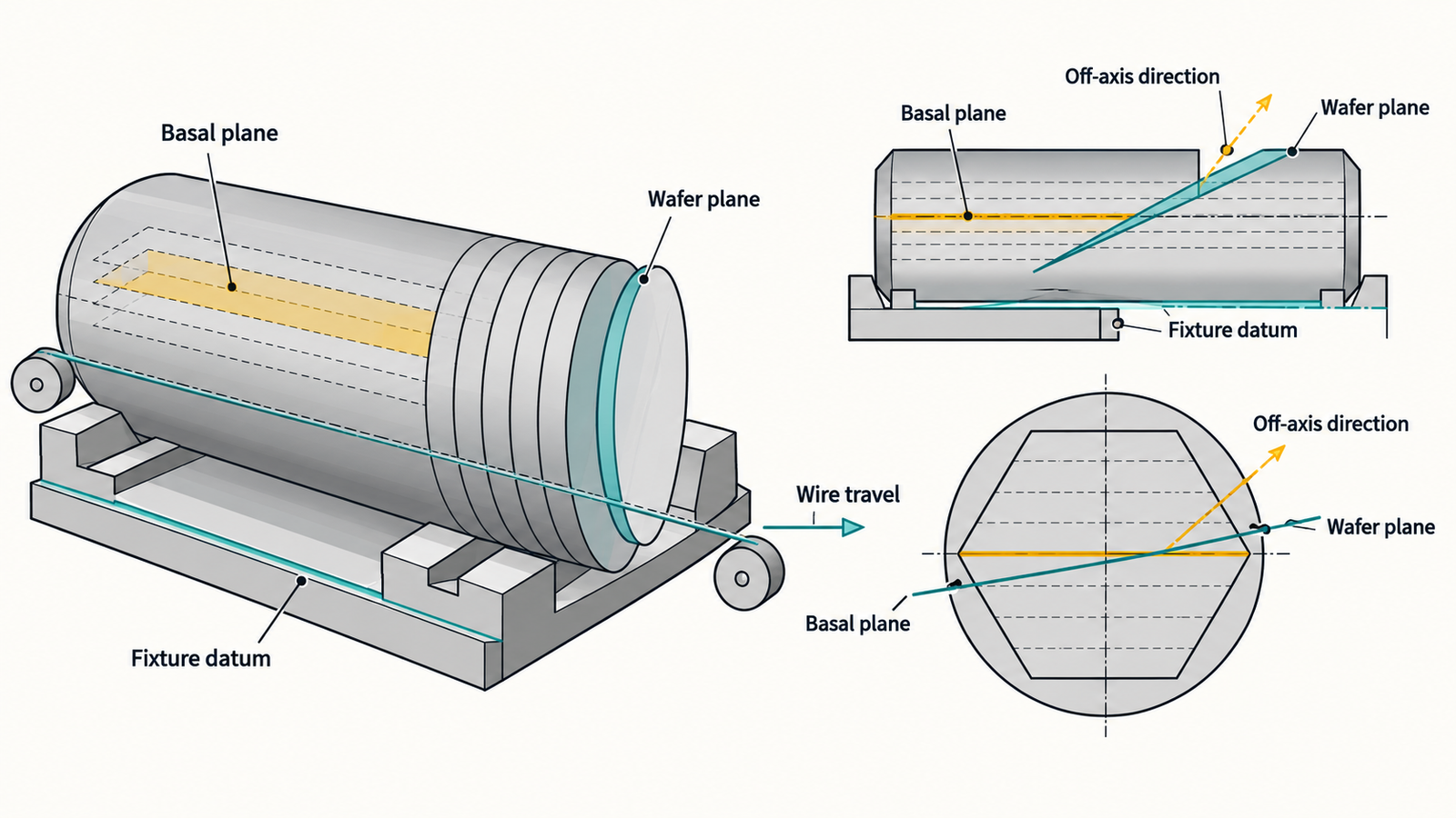
Failure patterns caused by uncontrolled orientation
Repeatable chipping in one wafer sector
If chips cluster near the same clock position over repeated cuts, preserve the boule orientation before changing the entire recipe. The pattern may identify a crystal-direction effect, local defect population or fixture-support transition. Photographing only the largest chip discards the spatial evidence.
Directional saw marks and waviness
Wire bow and vibration can leave periodic or directional marks. Map the surface relative to wire travel and off-axis direction. A single Ra value cannot distinguish a stable directional texture from random particle recutting. For a useful process review, retain line profiles in at least the wire-travel and cross-wire directions.
TTV, bow and warp that change after rotation
TTV is a thickness measurement, while bow and warp describe wafer shape under specified reference conditions. They should not be used interchangeably. If a rotated boule changes the signed thickness map or wafer-shape pattern, the result is strong evidence that orientation belongs in the process model. See the practical SiC wafer metrology guide for measurement definitions and mapping discipline.
Unexpected finishing loss
A wafer can meet as-cut thickness yet require excessive grinding or lapping because the damaged layer is deeper in one zone. That loss should be counted as part of slicing performance. The correct economic measure is usable wafer thickness and accepted yield after the defined downstream sequence, not kerf width alone.
Build an orientation-aware cutting trial
A controlled trial does not need a large statistical program at the start. It does need traceability. Mark the boule with a durable coordinate reference and record the relationship among off-axis direction, notch or flat, fixture datum, feed direction and wire travel.
- Verify incoming orientation. Use the supplier certificate and the agreed orientation measurement. Do not infer the off-axis direction from an undocumented mark.
- Establish a baseline. Cut repeated wafers with the same mount, conditioned wire, coolant state and recipe.
- Rotate one controlled variable. Where material and equipment permit, compare defined crystal-to-wire orientations without changing feed, wire speed or support.
- Synchronize machine data. Export tension, drive load, feed position, wire speed, coolant temperature and alarms against cut depth.
- Map outputs. Record thickness, TTV, bow, warp, roughness profiles, edge chips and subsurface-damage evidence in the same coordinate system.
- Repeat at a later wire-life stage. A fresh-wire result alone does not show production robustness.
Use more than one boule or lot before setting a permanent recipe. Otherwise, an orientation effect can be confused with micropipe, dislocation, stress or diameter differences among boules.
How a precision diamond wire saw improves control
A fixed-abrasive precision diamond wire saw can reduce cutting force and kerf compared with broader abrasive processes, but the benefit comes from the whole system. Wire diameter, abrasive size, bond, tension stability, guide accuracy, feed control, coolant delivery and fixture stiffness act together.
For orientation-sensitive SiC, the machine should provide:
- repeatable workpiece datums so a marked off-axis direction can be loaded consistently;
- stable wire speed and closed-loop tension without large transient overshoot;
- programmable feed profiles that respond to contact-length changes;
- coolant delivery reaching both entry and exit zones without deflecting the wire;
- process data export with sufficient time resolution to locate force events;
- fixture access that supports the final ligament and limits exit chipping.
A finer wire may reduce geometric kerf, but it also has less bending and tensile margin. If it bows, vibrates or breaks, total material loss rises. Select wire using accepted-wafer results, following a structured diameter, grit and bond comparison.
Endless versus multi-wire slicing for off-axis SiC
An endless diamond wire saw is useful for crystal-orientation studies, process coupons, small lots, defect sampling and special cuts. The accessible work zone makes it practical to rotate a marked sample, change support and observe one cutting interface. It is a development tool when the objective is understanding cause and effect.
A diamond multi-wire saw is intended for parallel wafer production. Its productivity advantage is meaningful only when orientation, web pitch, guide-groove condition, lane tension, coolant distribution and unloading are controlled. Retain each wafer’s lane and boule position. Pooling all wafers into one average can hide edge-lane drift or a repeatable crystal-sector pattern.
The two architectures should not be compared by wire speed alone. For R&D, compare learning rate, fixture flexibility and measurement access. For production, compare accepted wafers per boule, finishing removal, consumable cost, uptime and lot-to-lot consistency.
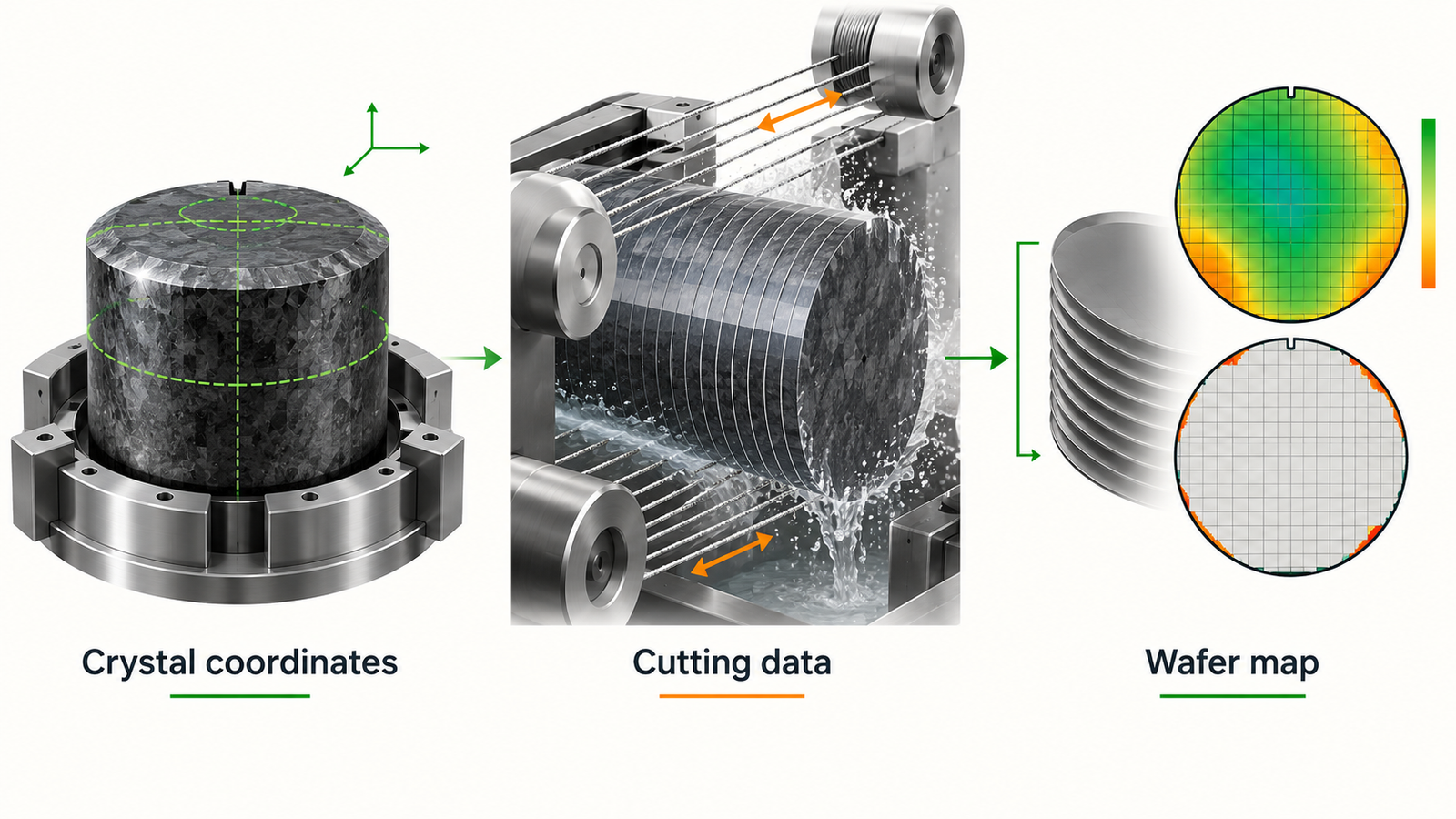
A production control plan
| Control item | Record | Reaction |
|---|---|---|
| Boule identity and orientation | Lot, polytype, off-axis angle/direction, datum photo | Hold material if marks and certificate disagree |
| Mounting | Fixture ID, adhesive/support, clock position | Reload before cutting if datum is outside tolerance |
| Wire state | Wire lot, diameter, exposure, conditioning cuts | Use defined replacement or investigation limit |
| Machine response | Tension, load, feed, speed, coolant temperature | Pause on correlated trend, not one noisy sample |
| Wafer geometry | Thickness map, TTV, bow, warp, lane and sequence | Segregate directional or position-dependent drift |
| Damage | Chip map, roughness profiles, sampled SSD method | Adjust support/feed and verify finishing allowance |
Control limits should come from capability data linked to the downstream specification. Copying a limit from a different diameter, orientation or metrology method creates false confidence.
Questions for equipment and process suppliers
- How is the off-axis direction located and transferred into the fixture datum?
- Can the trial compare defined orientations without changing other parameters?
- Which machine signals are exported, and can they be aligned with cut position?
- How are edge chips, TTV, bow, warp and subsurface damage measured?
- Does the acceptance run include conditioned wire and more than one boule?
- What support is provided when the material diameter or orientation tolerance changes?
How ewirexon supports SiC orientation studies
Ewirexon develops endless diamond wire saw and diamond multi-wire saw solutions for SiC and compound-semiconductor processing. For orientation-sensitive work, the useful starting point is a drawing and material packet: boule dimensions, 4H-SiC grade, off-axis specification, datum convention, target wafer thickness, edge exclusion, finishing route and planned volume.
A sample cutting trial can then preserve crystal coordinates, test support and feed strategies, and produce evidence for equipment selection. The objective is not to claim one universal recipe. It is to convert orientation from an uncontrolled material attribute into a documented process variable.
Conclusion
4° off-axis SiC improves the substrate’s suitability for epitaxial device manufacturing, but it also gives the slicing team a directional material. When crystal coordinates are lost at mounting, changes in chipping, waviness, TTV and finishing loss become difficult to explain.
Precision diamond wire saw technology provides a low-force, narrow-kerf platform for SiC wafer slicing. Its full value appears when orientation, machine data and wafer maps share one coordinate system. That traceability lets engineers tune the process, lets procurement compare realistic acceptance results, and protects expensive SiC material from avoidable learning cycles.
Frequently asked questions
Why are many 4H-SiC wafers cut 4° off-axis?
The intentional off-axis surface supports controlled step-flow behavior during epitaxial growth. The exact angle and direction depend on the substrate and device specification.
Does crystal orientation affect diamond wire saw cutting?
Yes. SiC has direction-dependent mechanical and fracture behavior. The relationship among off-axis direction, wire travel and feed can influence cutting force, chips, waviness and subsurface damage.
Can one SiC wafer cutting recipe work for every boule?
Not reliably. Diameter, orientation tolerance, defect population, resistivity class, wire condition and mounting all matter. A baseline recipe should be qualified across representative lots.
Is an endless diamond wire saw suitable for 4° off-axis SiC?
It is well suited to orientation studies, small lots, samples and special cuts. Production wafer volumes may justify a diamond multi-wire saw after lane consistency and handling are qualified.
Which measurements are most useful after SiC substrate slicing?
Use thickness maps, TTV, bow, warp, directional roughness, edge-chip maps and a validated subsurface-damage method. Keep all results referenced to the crystal and cutting directions.
Technical references
- Study of 4° off-axis 4H-SiC slicing and anisotropic behavior, 2026.
- Comparison of laser and wire-saw slicing for 8-inch 4° off-axis 4H-SiC, 2026.
- Crystal-orientation effects in 4H-SiC material processing, 2026.
Editorial note: Process recommendations should be verified on the actual crystal grade, orientation, diameter and downstream route. The figures are AI-generated engineering illustrations, not customer installations or certified crystal drawings.