
Silicon carbide wafer quality begins before a boule reaches the slicing department. Crystal-growth furnaces rely on graphite heaters, crucibles, insulation supports, seed holders and other carbon components that operate in severe thermal environments. Their geometry, purity and surface condition can affect furnace stability, contamination and maintenance intervals.
Isostatic graphite is widely used because it combines high-temperature capability, machinability and relatively uniform properties. It is also porous, dusty and easy to damage at thin edges. Conventional sawing and milling can waste material or create heavy cleanup. A diamond wire saw offers a low-force, narrow-kerf route for separating plates, rings and blanks before final machining.
The goal is not merely a fast graphite cut. For SiC crystal growth, the component must enter the furnace with controlled dimensions, surface integrity and contamination history. This guide connects cutting decisions to that final requirement.

Why graphite quality matters in SiC crystal growth
Physical vapor transport and related SiC growth processes run at high temperature. Graphite components help generate and shape the thermal field, contain source material and support the seed or insulation structure. Dimensional change, particle release or impurity transport can disturb the process.
Relevant graphite properties include bulk density, open porosity, grain size, ash or elemental impurities, thermal conductivity, coefficient of thermal expansion and strength. Coated components add coating thickness, adhesion and defect requirements. Two black blocks can differ substantially in how they cut and perform.
Recent industry standardization for isostatic graphite used in SiC single-crystal growth reflects the need for clearer material and testing definitions. Cutting trials should preserve the supplier grade and lot so geometry results are not separated from material properties.
Why graphite cutting deserves a controlled process
Graphite is softer than SiC, but that does not make it trivial. Its porous microstructure can crumble at edges. Fine conductive dust migrates into bearings, electrical enclosures, coolant systems and other production areas. Thin rings can distort under clamps. Internal pores and density variation can change local removal behavior.
Common problems include:
- wide kerf and low blank yield from expensive purified stock;
- edge breakout that consumes machining allowance;
- taper or waviness caused by low wire tension, loading or fixture movement;
- dust embedded in pores or redistributed onto clean surfaces;
- metallic contamination from tools, fixtures and shared coolant;
- coating damage when already coated components are modified.
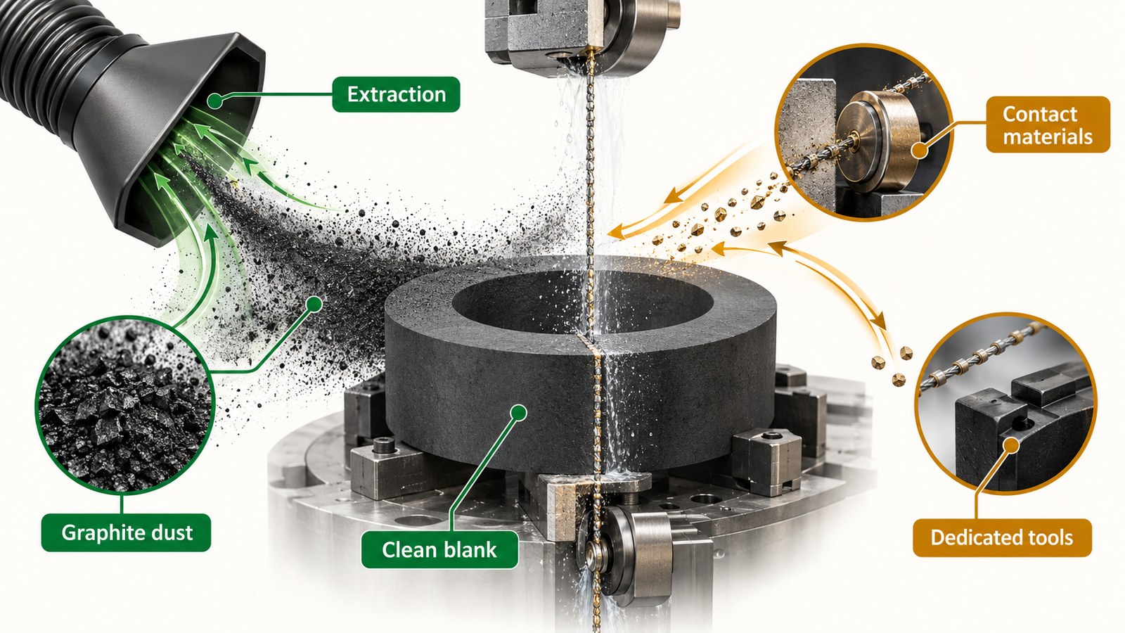
Graphite dust is not just a housekeeping issue. It is part of equipment reliability and contamination control. The cutting cell, extraction method and cleaning flow belong in the process specification.
Where diamond wire saw cutting adds value
Diamond wire cutting is well suited to blanking graphite blocks, separating plates, slicing rings from a tube or cylinder, and preparing near-net pieces for CNC machining. The distributed cutting action produces low reaction force, which is useful for fragile sections and thin walls. Narrow kerf can increase the number of blanks recovered from a purified billet.
It is not a replacement for every machining operation. Precision bores, threaded features, sealing faces and complex three-dimensional geometry normally require milling, turning, grinding or electrical methods appropriate to the grade. Wire cutting should remove bulk material while leaving a predictable finishing allowance.
For a make-or-buy decision, calculate recovered component area or volume per billet, total machining time, dust collection, wire life, finishing stock and reject rate. A narrow cut has little value if it leaves taper that requires heavy milling.
Dry cutting versus wet cutting
Graphite may be cut dry with extraction or wet with a compatible fluid system. Each route has trade-offs.
| Method | Advantages | Risks to control |
|---|---|---|
| Dry cutting | No drying step; avoids liquid uptake | Airborne conductive dust, heat, visibility and extraction loading |
| Wet cutting | Captures particles and cools interface | Fluid absorption, residue, tank contamination and drying validation |
The correct method depends on graphite porosity, purity requirement, later purification or coating, and facility controls. If wet cutting is used, define water or fluid quality, filtration, tank segregation, drying temperature and endpoint. If dry cutting is used, verify capture velocity, filter class, grounding and protection of moving and electrical components.
Do not switch between graphite and semiconductor quartz or SiC in one fluid loop without a documented cleaning validation. Carbon fines can persist in hoses, tank corners and filter housings.
Wire and parameter selection
Graphite removes differently from hard crystals. An overly coarse or aggressive wire can tear weak edges, while an excessively fine wire can load with carbon and rub. Start with representative density and grain size, then evaluate wire diameter, abrasive size, bond and open chip space.
Key signals include drive load, wire tension response, cut time, wire appearance and debris behavior. Plot them against contact length. Rising load at constant engagement may indicate loading, extraction loss or wire wear. A falling load with poorer geometry may indicate local crumbling rather than efficient cutting.
Feed profiles should protect entry and exit edges. Reduce clamp pressure on thin rings and support the final ligament. The fixture should use clean, compatible contact materials and avoid point loads. Preserve component orientation if the billet has documented property direction or density gradients.
Control dust and contamination at the source
Design the cell so dust does not rely on an operator’s final wipe. Enclose the cutting zone, capture particles near generation and make surfaces accessible for cleaning. Protect guides, tension sensors, bearings and electrical cabinets. Trend extraction differential pressure or coolant filtration rather than waiting for visible accumulation.
For high-purity components, create a contact-material list. Include wire core and bond, guide wheels, fixture plates, adhesives, gloves, trays and cleaning media. If metallic contamination limits are important, verify them after the complete cutting and cleaning route using a method agreed with the crystal-growth owner.
Separate tools and storage by graphite grade and coating state. A coated susceptor or ring may require different handling from an uncoated machining blank. Avoid presenting “clean graphite” as one universal condition.

A qualification plan for SiC growth components
- Define the final component. Supply the drawing, graphite grade, purity, coating plan, functional surfaces and furnace location.
- Map the manufacturing route. Identify which faces are wire cut, CNC machined, purified, coated or inspected later.
- Cut representative coupons and blanks. Include maximum contact length and minimum wall sections.
- Measure geometry. Check thickness, parallelism, taper, flatness, edge breakout and finishing allowance.
- Assess cleanliness. Verify dust removal, drying and relevant elemental or particle limits.
- Test coating compatibility. Where coating follows, confirm adhesion and defect levels on the qualified pre-coat surface.
- Run handling simulation. Include unloading, transport, cleaning and assembly contacts.
- Close the furnace feedback loop. Track component life and any contamination or thermal-field observations by manufacturing lot.
Furnace performance is influenced by many variables, so do not attribute a growth result to cutting from one run. The useful objective is traceability: if a component problem appears, its material, cutting, cleaning, purification and coating history can be reconstructed.
Endless and multi-wire options for graphite
An endless diamond wire saw for graphite suits blocks, plates, rings, prototypes and changing component dimensions. It offers flexible fixturing and can support dry or wet process development depending on machine configuration.
A diamond multi-wire saw can improve throughput when a graphite billet must become many parallel plates. The business case depends on stable web spacing, dust or fluid management and safe removal of thin parts. Lane-level thickness and edge data should be retained during qualification.
For recurring special components, customized fixtures may provide more value than maximum nominal machine speed. A fixture that reduces breakage and setup variation improves accepted output even if the cut itself is not faster.
Questions for a graphite cutting equipment review
- Which graphite grades, densities and part geometries have been demonstrated?
- How are conductive dust and fine particles kept away from bearings and electronics?
- Can the fluid loop or extraction system be dedicated to graphite?
- What fixture supports thin rings and the final exit section?
- How are taper, flatness, edge breakout and surface condition measured?
- Which contact materials can introduce metallic or polymer contamination?
- What cleaning and preventive-maintenance time is included in capacity?
How ewirexon supports graphite component cutting
Ewirexon provides endless diamond wire saw and related cutting solutions for graphite, carbon materials, ceramics and semiconductor crystals. Its graphite cutting application guidance covers narrow-kerf, low-force preparation of blocks and special components.
For a SiC crystal-growth program, useful project inputs include graphite grade, billet and finished dimensions, thin-wall risks, purity and coating requirements, planned finishing, annual mix and facility dust controls. A sample trial can then compare material yield and edge condition while the cleaning and contamination plan is developed in parallel.
Conclusion
Graphite components are part of the process environment that shapes SiC crystal growth. Their manufacture deserves the same traceability applied to the wafer. Diamond wire saw cutting can reduce kerf and reaction force during blank preparation, especially for plates, rings and fragile sections.
The successful process controls dust, contact materials, geometry and downstream finishing together. Evaluate equipment by clean accepted blanks per billet and by the stability of the entire manufacturing route. That approach supports both component yield and the much higher-value crystal-growth process downstream.
Frequently asked questions
Why is graphite used in SiC crystal-growth furnaces?
Graphite tolerates high temperatures and provides useful thermal, structural and machining properties for heaters, crucibles, insulation structures and supports.
Can a diamond wire saw cut isostatic graphite?
Yes. It is useful for low-force blanking, plate and ring cutting. The wire, fixture and dust or fluid controls should be matched to the exact graphite grade.
Is dry or wet graphite cutting better?
Neither is universal. Dry cutting needs effective conductive-dust extraction; wet cutting needs fluid segregation, residue control and validated drying.
How does diamond wire cutting reduce graphite waste?
A narrow kerf and low-force separation can recover more blanks from a billet and reduce edge breakout. Total yield must include taper and downstream machining stock.
What should be checked before cutting graphite for semiconductor use?
Confirm grade, density, purity, coating plan, functional surfaces, contamination limits, cleaning route and fixture support. Preserve lot traceability through furnace use.
Technical references
- SGL Carbon, graphite applications in semiconductor crystal growth.
- SGL Carbon, coated graphite susceptors for semiconductor processing.
- Release of isostatic graphite standards for SiC single-crystal growth.
Editorial note: Furnace performance and contamination limits are application-specific. The figures are AI-generated engineering illustrations, not customer furnace components or certified equipment drawings.