









NdFeB permanent magnets enable electric traction motors, industrial servos, wind turbines, robotics, medical equipment, and data-center hardware. The IEA’s 2026 analysis says demand for magnet rare-earth elements has doubled since 2015 and is expected to grow by another third by 2030 under current policy settings. Material utilization and reliable finishing are therefore procurement concerns, not just machining details.
Sintered neodymium-iron-boron is commonly cut after sintering and heat treatment but before coating and magnetization. Its microstructure is brittle: a slice can meet nominal thickness while carrying waviness, pits, chipped corners, or damage that increases grinding and coating risk.
A diamond wire saw uses many fixed diamond grains along a narrow tool. It can support low kerf and controlled force, but feed, speed, tension, guide dynamics, coolant, fixturing, and wire wear determine whether it creates accepted segments or moves cost into grinding.
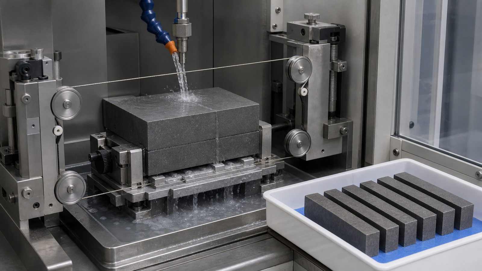
Put NdFeB magnet cutting in the correct process sequence
A typical route includes powder preparation, alignment and pressing, sintering, heat treatment, machining, cleaning, surface protection, magnetization, and inspection. Exact sequences vary. For cutting, establish whether the workpiece is magnetized, coated, or bonded.
Whenever design permits, slice before final magnetization. A magnetized workpiece attracts debris, tools, and machine components, complicating cleaning, safety, and fixturing. Cutting a finished coating also exposes an edge that may need renewed protection. Disclose either condition during process review.
Motor segments, thin plates, and R&D coupons create different contact lengths and support conditions. Grade, grain orientation, alloy additions, density, and prior grinding also affect fracture. A drawing that says only “NdFeB” is insufficient.
Why sintered NdFeB is difficult to cut consistently
Sintered NdFeB contains hard magnetic Nd2Fe14B grains and rare-earth-rich boundary phases. Under an abrasive, removal shifts among rubbing, ploughing, small-scale fracture, grain loosening, and breakout. A uniformly gray surface can therefore hide different roughness, waviness, pits, and subsurface condition.
Three characteristics make the process window narrow:
- Brittle fracture: aggressive abrasive penetration or unsupported edges can release grains and create pits, microcracks, and corner chips instead of a controlled chip.
- Low resistance to environmental attack: unprotected NdFeB can oxidize or corrode. Coolant chemistry, exposure time, cleaning, drying, and temporary storage must be part of the machining route.
- High material value: excessive kerf, rejected segments, and added grinding consume rare-earth-containing stock that has already passed energy-intensive upstream processing.
A recipe demonstrated on a small N35 sample cannot be transferred directly to a larger contact area, another grade, or a multi-wire web.
Roughness and waviness are different problems
Roughness describes short-wavelength texture; waviness describes longer variation. A surface can have acceptable Ra and still need substantial grinding because peak-to-valley waviness is large. Calling both “finish” hides the mechanism.
A peer-reviewed NdFeB study found lateral wire swing was the main cause of periodic waviness in its test system and that peak-to-valley waviness increased with normal cutting force. When regular waves appear, investigate force and lateral motion before changing only grit or polishing allowance.
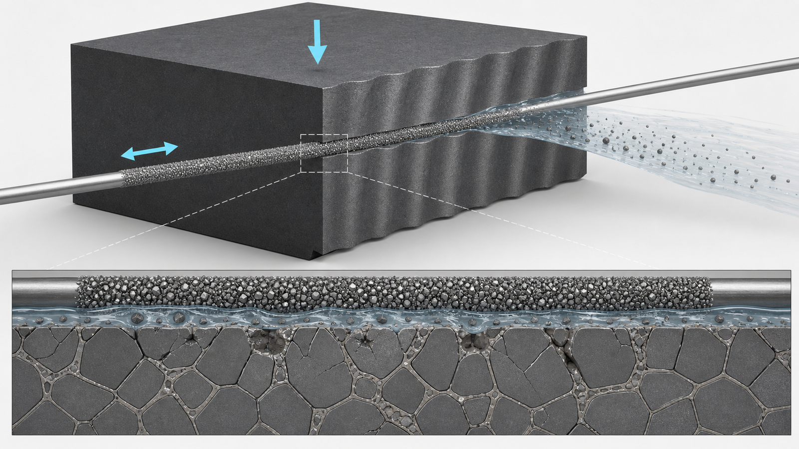
Common NdFeB cutting defects and their cost
| Observed defect | Likely process questions | Production consequence |
|---|---|---|
| Periodic waviness or saw marks | Is normal force high? Does the period match drive reversal, guide rotation, or another machine frequency? Is lateral wire motion visible? | More grinding stock, thickness loss, longer cycle, or rejected thin parts |
| Edge chipping | Is entry contact stable? Is the exit ligament supported? Does the fixture introduce bending? | Reduced usable area, coating difficulty, crack origin, sorting labor |
| Large pits or grain pullout | Is abrasive engagement too aggressive? Is the wire in a poor wear stage? Is debris recutting the surface? | Poor cut-face integrity and increased finishing removal |
| Thickness variation or taper | Is the wire bowing as contact length changes? Are guides aligned? Is part support symmetric? | Lower dimensional yield and nonuniform grinding allowance |
| Excessive kerf | Does effective wire envelope include lateral vibration, runout, and grit protrusion? Is the cut wandering? | Fewer segments per block and higher material cost per accepted part |
| Wire breakage | Is feed force rising? Are guides damaged or radii too small? Is debris loading the kerf? Is tension leaving enough fatigue margin? | Downtime, damaged workpiece, rethreading, and possible batch loss |
| Staining or corrosion after cutting | Is the fluid compatible and inhibited? Are rinse, dry, and storage times controlled? | Coating adhesion risk, cosmetic rejection, or magnetic performance concern |
How to reduce cutting force without creating a weak process
Balance feed rate and wire speed
Feed increases removal demand; if abrasive capacity does not keep up, force, bow, and brittle breakout rise. More wire speed can spread the work and improve debris transport, but it also changes dynamics, coolant behavior, and wear. Optimize the ratio and force trend.
At baseline, use conservative feed, documented wire condition, and sufficient coolant. Record load, visible bow, cut time, and surface results as contact length grows. A sharp force increase calls for a debris and wire check, not automatically more motor power.
Use tension to control the path, not to mask excessive feed
More tension can reduce deflection but consumes tensile and fatigue margin; it changes the wire’s response rather than removing cutting force. Calibrate tension, inspect guides and bearings, and verify no-load tracking.
Control fixture stiffness and the final ligament
Support the block close to the cut without distortion. Control adhesive bond-line, cure, compatibility, and release. Support thin segments on both sides so the final ligament cannot rotate into the wire. Inspect entry and exit separately.
Deliver compatible coolant into the active kerf
Wet cutting improves cooling and debris transport, but ordinary water is not automatically acceptable for unprotected NdFeB. Select a fluid and corrosion-control package compatible with the grade, machine, coating route, and environmental rules. Control concentration, temperature, filtration, rinse, drying, and protected-storage delay.
The nozzle must reach the deepest active contact; a wet exterior with a debris-packed kerf is not effective cooling. Handle fine alloy debris under facility procedures even when the workpiece is unmagnetized.
Wire wear is a process variable, not only a consumable cost
A 2024 study found that its stable wire-wear stage produced better NdFeB surfaces than the early stage, while late wear included flattened or lost grains. Within its tested ranges, lower feed, higher wire speed, and smaller workpiece size improved roughness and waviness.
Establish acceptance by cumulative cutting area or another validated wear indicator. Include new-wire, stable-life, and end-of-life behavior. A replacement criterion tied to force, waviness, damage, and breakage risk is more useful than maximum-life marketing.
Build an NdFeB cutting trial around measurable outputs
Freeze the grade, supplier lot, available density or microstructure data, orientation, block size, surface, coating, and magnetization status. Then define finishing and acceptance limits.
- Verify the machine mechanically. Check pulley condition, alignment, runout, tension calibration, coolant delivery, fixture stiffness, and no-load vibration.
- Establish a documented baseline. Use representative stock and record wire batch, wire life, feed, speed, tension, coolant state, cut time, load trend, and operator observations.
- Measure different length scales separately. Report roughness, filtered waviness or profile PV, thickness variation, taper, kerf, chip size, and pit population with agreed methods.
- Change one parameter family at a time. Explore feed-to-speed balance first, then tension region, wire specification, support, or coolant. Use a designed experiment after a stable region is found.
- Repeat across wire life and material position. A successful center coupon with a fresh wire does not establish process capability.
- Include post-cut handling. Apply the planned rinse, dry, storage, grinding, and coating sequence before declaring the cut acceptable.

Endless diamond wire saw or diamond multi-wire saw?
An endless diamond wire saw suits development, high-value cuts, mixed geometries, prototypes, and smaller batches. A desktop endless loop diamond wire saw can prepare coupons and small segments when fixture, wire range, and work envelope fit. Its value is flexibility and observable single-cut behavior.
A diamond multi-wire saw makes parallel cuts and reduces handling in stable volume production. Coolant distribution, web tension, pitch, bow, flatness, and unloading all affect batch yield. Scale only after the single-cut process and tolerance stack are understood.
| Decision factor | Endless / desktop endless loop | Diamond multi-wire |
|---|---|---|
| Primary objective | Flexibility, R&D, prototypes, special profiles, controlled single cuts | Parallel slicing, repeat volume, lower handling per slice |
| Changeover | Generally easier for mixed parts and fixtures | Best when geometry and pitch are stable |
| Process visibility | Useful for isolating force, fixture, and surface mechanisms | Requires web-level monitoring and uniform fluid delivery |
| Main scaling risk | Cycle time per part | Multiplying thickness, waviness, or wire-breakage variation across the batch |
What procurement teams should request
Beyond size, power, nominal accuracy, and price, ask for the material and geometry behind each performance claim, its measurement method, and whether results cover one cut or repeated runs.
A useful request for quotation includes target accepted parts per block, kerf definition, thickness and parallelism limits, maximum chip size, waviness filter and limit, roughness method, finishing allowance, coating route, fluid restrictions, expected annual volume, changeover mix, and required traceability. Request a representative material trial and an acceptance report that preserves raw measurement data.
Ewirexon’s magnetic material and special crystal slicing application, broader diamond wire saw portfolio, and process parameter consulting are relevant starting points for NdFeB trials. Projects involving unusual segment profiles, magnetized assemblies, or dedicated automation may require custom equipment development. The machine format should be selected after the material condition, acceptance method, and volume are clear.
Conclusion
Rising NdFeB demand makes kerf loss reduction, accepted-part yield, and finishing allowance meaningful business metrics. A diamond wire saw can address them only when force, lateral motion, support, coolant, and wire life are controlled together.
Periodic waviness is especially useful as a diagnostic signal. Research connects it to lateral wire swing and normal cutting force, so it should not be hidden inside one roughness result. Likewise, a low nominal kerf is not a success if vibration widens the effective cut or edge damage forces more grinding.
For a credible equipment trial, provide the NdFeB grade and lot, orientation, block and segment dimensions, coating and magnetization state, dimensional and surface limits, finishing route, coolant restrictions, and annual volume. Those inputs allow endless and multi-wire options to be judged by accepted material output rather than brochure specifications.
FAQ
What is the best cutting method for sintered NdFeB magnets?
For many block-to-segment and plate-slicing operations, a fixed-abrasive diamond wire saw offers a useful balance of kerf, cutting force, and geometry flexibility. The best method still depends on magnet grade, part size, thickness, coating and magnetization state, finishing allowance, and production volume.
Why does periodic waviness appear during NdFeB magnet cutting?
Periodic waviness can be printed by lateral diamond-wire motion. Research on NdFeB diamond wire sawing found lateral swing to be the main cause in the tested system and linked larger waviness to higher normal cutting force. Guide runout, reciprocation or rotation frequencies, fixture dynamics, feed, and wire condition should be investigated.
Should NdFeB be cut before or after magnetization?
Cutting before final magnetization is generally preferable when the product route allows it. Magnetized parts attract debris and ferromagnetic objects and create additional cleaning, fixturing, and safety challenges. Any cutting of a magnetized assembly requires an application-specific review.
How does a diamond wire saw reduce NdFeB material loss?
A fine diamond wire can create a narrow cutting path, but actual material loss includes grit envelope, wire runout, lateral vibration, and finishing stock. Kerf loss reduction therefore requires stable tracking, controlled force, suitable wire life, and edge quality that does not demand excessive grinding.
When should a diamond multi-wire saw be used for magnetic material slicing?
A diamond multi-wire saw is appropriate when many parallel slices of a stable geometry are required and the single-cut process is already capable. Confirm wire-web tension, coolant uniformity, pitch, unloading, thickness distribution, and breakage response with representative blocks before production release.
Technical sources
- International Energy Agency: Rare Earth Elements executive summary (2026)
- Experimental and Theoretical Investigations on Diamond Wire Sawing for a NdFeB Magnet
- Surface characteristics of precision as-cut NdFeB magnet considering diamond wire wear
- Process Parameters Analysis in Diamond Wire Saw Cutting NdFeB Magnet
Editorial note: This article was developed with AI-assisted research and English editing. Technical statements were checked against the cited primary sources and Ewirexon’s published application information. The illustrations are AI-generated conceptual visuals, not customer process photographs or measured test results. Process values and method selection must be validated with representative material.