










Aluminum nitride (AlN) has moved from a specialist ceramic to a strategic substrate material for high-power electronics. Its combination of electrical insulation and high thermal conductivity makes it valuable in power modules, high-power LEDs, RF devices, and thermal management assemblies. The manufacturing pressure around these applications is increasing. The International Energy Agency reported in 2026 that electricity use by AI-focused data centers grew 50% in 2025, while power density and thermal loads continued to rise. That trend does not make every AlN component an AI product, but it does raise the value of reliable ceramic substrates and packaging processes.
Cutting is one of the first places where that value can be lost. A slice may meet its nominal thickness and still contain edge chips, deep saw marks, local waviness, or subsurface cracks that appear during lapping, metallization, thermal cycling, or assembly. A diamond wire saw can reduce cutting force and kerf compared with many rigid tools, but only when the wire, fixture, coolant, and feed strategy are qualified as one process.
This guide provides a practical qualification method for process engineers and equipment buyers. It intentionally does not publish a universal wire speed, tension, or feed rate. Those numbers depend on the AlN grade, blank geometry, diamond wire construction, machine dynamics, and acceptance criteria. Values copied from another plant can be worse than no starting point at all.
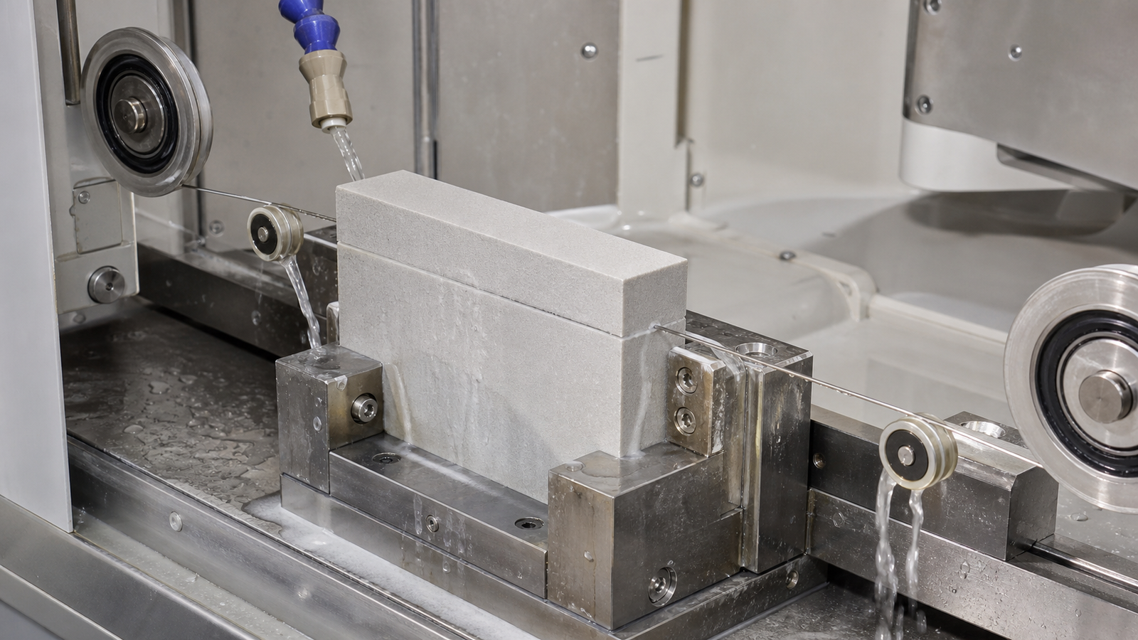
First define which AlN cutting operation you are qualifying
“AlN substrate cutting” can describe several very different operations. Mixing them in one equipment specification is a common procurement error.
- Blank or ingot slicing: producing plates or wafers from a thick fired AlN body. Kerf, parallelism, wire bow, and subsurface damage are primary concerns.
- Coupon preparation: cutting small specimens for material development, metallization trials, reliability testing, or failure analysis. Flexibility and repeatable fixturing matter more than maximum throughput.
- Profile or component cutting: separating thick or irregular ceramic parts. Access, contour capability, and local support can dominate the process.
- Final singulation of thin metallized substrates: separating finished circuits or packages. Depending on thickness, metallization, feature spacing, and volume, a precision blade, laser, scribe-and-break process, or another dicing method may be more appropriate than wire sawing.
A wire saw should therefore be evaluated against the actual process step, not against the broad statement that AlN is hard and brittle. For thick blanks, expensive material, low-stress coupon preparation, and flexible geometries, diamond wire cutting can offer a useful process window. It is not automatically the best tool for every finished substrate.
Why AlN does not behave like an ordinary structural ceramic
AlN is difficult to machine because it combines high hardness with limited tolerance for tensile stress. Material removal by fixed diamond abrasives can include rubbing, ploughing, microfracture, and chip formation. If the instantaneous penetration of active grains becomes too aggressive, cracks can extend below the visible surface. If penetration is too low, the wire may rub, load with debris, generate heat, and lose cutting efficiency.
Recent research on diamond wire sawing of AlN found that wire vibration changed both removal efficiency and surface damage. The study connected winding frequency, lateral micro-oscillation, brittle removal, and subsurface damage rather than treating speed as an isolated setting. That is an important production lesson: a higher displayed speed does not necessarily mean a more stable cutting condition.
Commercial AlN ceramics also vary. Density, grain structure, secondary phases, binder chemistry, porosity, thermal treatment, and crystal orientation can all change the way a nominally identical part cuts. Procurement documents should identify the material grade and manufacturing state, not merely state “AlN ceramic.”
Set measurable critical-to-quality outputs before adjusting the saw
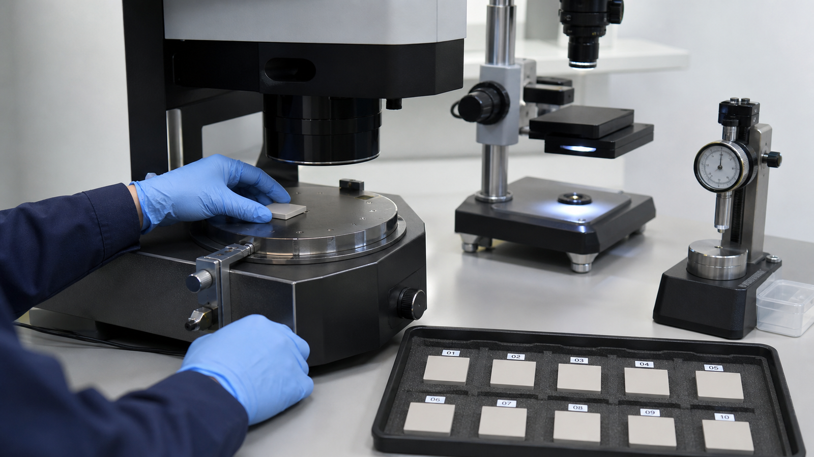
A useful qualification begins with acceptance metrics. “Smooth surface” and “low chipping” are not measurement plans. Define how each result will be measured, where it will be measured, and what happens when measurements disagree.
| Quality output | Why it matters | Practical measurement approach |
|---|---|---|
| Slice thickness and TTV | Controls downstream lapping allowance and final component uniformity | Map multiple points rather than reporting one center reading |
| Kerf width | Determines material yield and influences chip evacuation | Measure at entry, middle, and exit when geometry permits |
| Edge chipping | Can reduce usable area and initiate later fracture | Record maximum chip size and affected edge length under fixed magnification |
| Surface roughness and waviness | Influence lapping time and indicate vibration or wire-mark behavior | Measure in more than one direction and keep roughness separate from waviness |
| Subsurface damage | May remain invisible until polishing or reliability testing | Use a validated destructive sample method or microscopy plan for qualification lots |
| Cut time and wire consumption | Convert technical quality into cost per accepted part | Track accepted output, not only machine cycle time |
Do not optimize surface roughness alone. A setting that produces a visually uniform surface may still create waviness, excessive kerf, or hidden cracks. Likewise, the fastest cut is not productive if it increases polishing stock or rejects.
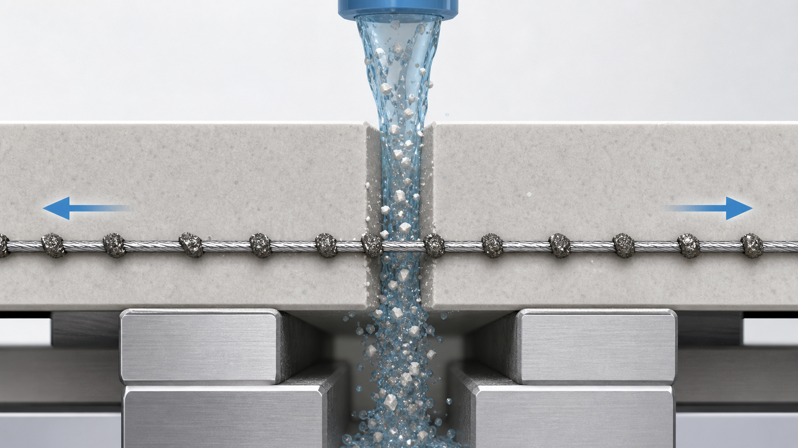
Build the qualification around five interacting controls
1. Wire specification
Core diameter, overall envelope, diamond grit size, grit distribution, protrusion, bond type, and loop or spool construction all affect the cut. A smaller wire envelope may reduce theoretical kerf, but it also changes tensile capacity, stiffness, coolant access, and sensitivity to guide condition. Selecting the thinnest available wire without checking load margin is not a kerf-loss strategy.
For qualification, record the wire batch and initial condition. Inspect a representative section before cutting so later wear, loading, grit pullout, or localized damage can be compared with a baseline.
2. Wire speed, feed rate, and wire bow
Wire speed and feed rate determine how much material each active abrasive must remove. Increasing feed without sufficient cutting capacity raises normal force and wire bow. Increasing speed can distribute work across more abrasive contacts, but excessive dynamic excitation may worsen lateral motion and surface marks. Use machine load, wire bow, cut time, and surface data together.
A practical first experiment keeps the wire and fixture constant, establishes a conservative baseline, and changes one parameter family at a time. Once a stable region is found, a small designed experiment can examine interactions. Avoid changing tension, feed, coolant, and wire type in the same trial; a good result will be impossible to explain or reproduce.
3. Tension and wire-path alignment
Tension must be high enough to control bow and tracking, but below a level that consumes too much of the wire’s tensile and fatigue margin. The displayed setpoint is only useful if the tension system is calibrated and the wire path is aligned. Guide groove wear, contamination, bearing condition, and roller runout can create local bending stress even when the nominal tension looks correct.
Run the wire without workpiece contact and observe tracking before every important qualification series. A no-load instability should be corrected mechanically before process parameters are changed.
4. Coolant delivery and debris evacuation
Coolant removes heat and transports AlN debris out of the kerf. The nozzle must deliver fluid into the active contact zone, not merely wet the top of the workpiece. As the cut deepens, access changes. Flow that is adequate at entry may become insufficient near maximum contact length.
Check fluid compatibility with machine components, fixtures, any metallization, and post-cut cleaning requirements. Monitor concentration, filtration, temperature, and visible debris loading. A blocked or recirculating kerf increases rubbing and can imitate the symptoms of an aggressive feed rate.
5. Fixturing and exit support
AlN should be supported without introducing bending stress. Uneven adhesive thickness, hard point contact, or clamp distortion can produce cracks that are incorrectly attributed to the wire. The final stage of a cut deserves special attention because the remaining section becomes less stiff and the separated part may move.
Use sacrificial support where appropriate, control adhesive cure and bond-line thickness, and define how the part is released after cutting. Photograph the fixture and record orientation so successful setups can be repeated.
A practical AlN process qualification sequence
- Freeze the material definition. Record grade, supplier lot, fired or green state, density information, geometry, surface condition, and any preferred cutting orientation.
- Define acceptance criteria. Set limits for thickness, TTV, kerf, edge chips, surface texture, subsurface damage sampling, and accepted-part cost.
- Verify the machine mechanically. Check guide condition, tracking, tension calibration, fixture stiffness, coolant delivery, and no-load vibration.
- Establish a conservative baseline. Use a fresh documented wire and enough coolant access. Record load, bow or deflection indicator, cut time, and observations throughout the cut.
- Change one control family. Evaluate feed-to-speed balance first, then tension or wire specification, while keeping the fixture and measurement method fixed.
- Repeat the selected condition. One acceptable coupon is feasibility evidence, not process capability. Repeat across material locations and, when possible, more than one material lot.
- Run an extended cut test. Confirm that wire wear, coolant contamination, and thermal drift do not move the process outside acceptance after repeated cycles.
Symptom-based troubleshooting during AlN cutting
| Observed symptom | Check first | Do not assume |
|---|---|---|
| Large chips at wire entry | Initial contact strategy, local support, wire vibration, exposed grit condition | That lower feed alone will remove the problem |
| Breakout at cut exit | Remaining-section stiffness, support layer, part movement, feed reduction near exit | That the entire cut uses the wrong wire |
| Periodic surface marks | Guide runout, wire oscillation, drive frequency, fixture resonance | That average roughness describes the defect |
| Increasing load during the cut | Contact length, debris evacuation, wire loading, coolant access, bow | That the motor or tension controller is faulty |
| Good first slices, poor later slices | Wire wear, fluid contamination, fixture drift, thermal stabilization | That the original settings remain capable indefinitely |
Choosing endless, desktop, or multi-wire equipment
An endless diamond wire saw is useful when the application requires flexible blank sizes, profile capability, low-stress single cuts, or frequent changes between materials. A desktop endless loop diamond wire saw can be a practical qualification platform for R&D coupons and small batches when its work envelope, wire range, and metrology plan match the intended scale.
A diamond multi-wire saw becomes relevant when multiple parallel slices and production consistency matter more than setup flexibility. It should be considered only after a stable single-cut process and a complete tolerance stack have been established. Multiplying an unstable cut across a wire web multiplies scrap rather than productivity.
For an AlN project, equipment buyers should send the supplier the blank dimensions, intended slice thickness, TTV and flatness targets, maximum chip allowance, surface requirement, annual volume, coolant restrictions, and downstream finishing route. Ewirexon’s AlN substrate slicing application, electronic ceramic substrate processing, and process parameter consulting pages provide useful starting points. Final machine and consumable selection should still be confirmed with representative material trials.
Conclusion
A precision diamond wire saw can create a low-stress, material-efficient route for AlN blank slicing and coupon preparation, but the machine is only one part of the process. Reliable results come from defining the operation correctly, measuring more than surface appearance, controlling wire-path dynamics, supporting the ceramic, and validating the process over repeated cuts.
The most useful request for quotation is therefore not “Please quote an AlN wire saw.” It is a process file containing material grade, blank size, slice thickness, tolerance map, edge criteria, surface requirement, production target, and downstream operations. That information allows an equipment supplier to recommend a defensible test plan rather than a generic parameter table.
FAQ: AlN substrate cutting with a diamond wire saw
Is a diamond wire saw always the best method for AlN substrate cutting?
No. It is well suited to thick blanks, low-stress slicing, expensive material, R&D coupons, and some irregular components. Thin metallized substrate singulation may be better served by precision blades, lasers, or other dicing methods depending on the circuit design and production volume.
Which parameter has the greatest effect on AlN edge chipping?
There is no single universal parameter. Abrasive engagement, feed-to-speed balance, lateral wire motion, fixture support, material microstructure, and entry or exit conditions interact. Diagnose the chip location and morphology before changing settings.
Does a thinner diamond wire always produce lower kerf loss?
It reduces the geometric contribution to kerf, but actual kerf also depends on abrasive protrusion, wire motion, tracking, wear, and debris clearance. A wire that is too flexible or overloaded can create a wider, less stable cut.
When should a diamond multi-wire saw be considered for AlN?
Consider it when the geometry requires repeated parallel slices, demand justifies batch processing, and a stable process window has already been demonstrated. TTV, wire-web consistency, coolant distribution, and wire replacement economics must be included in the decision.
What information is needed for an AlN cutting trial?
Provide the exact material grade and state, blank dimensions, required slice thickness, TTV or flatness limits, edge-chip allowance, surface target, cutting orientation, quantity, coolant restrictions, and downstream finishing steps.
Technical references
- International Energy Agency, Key Questions on Energy and AI, 2026.
- Liang et al., Surface damage mechanism and process control in diamond wire sawing of aluminum nitride, Diamond and Related Materials, 2026.
- Sefene, Chen, and Tsai, A comprehensive review of diamond wire sawing process for single-crystal hard and brittle materials, Journal of Manufacturing Processes, 2024.
Editorial note: This article was developed with AI-assisted research and English editing. Technical statements were checked against the cited primary literature and Ewirexon’s published application information. The illustrations are AI-generated conceptual visuals, not customer process photographs or measured test results. Process values must be validated with representative material.