










Three hundred millimeter silicon carbide is no longer only a conference-roadmap number. Coherent announced a 300 mm SiC platform milestone in December 2025, and Wolfspeed reported production of a single-crystal 300 mm SiC wafer in January 2026. These announcements do not mean that 300 mm SiC has already become a standard volume substrate. They do mean that process-development teams should start asking a harder question: what must a slicing process prove before a larger boule can be treated as a manufacturing platform?
The answer is not simply “use a wider machine.” Increasing diameter changes maximum contact length, sensitivity to wire bow, the distance coolant and debris must travel, fixture load and the area affected by a local disturbance. A 300 mm wafer has 2.25 times the nominal area of a 200 mm wafer and four times that of a 150 mm wafer. That opportunity matters only when accepted-wafer yield is stable.
This guide turns the 300 mm trend into an engineering and procurement checklist. It focuses on fixed-abrasive ダイヤモンドワイヤーソー qualification, while recognizing that commercial readiness will depend on crystal growth, orientation, defect control, grinding, polishing and downstream device requirements as well as slicing.
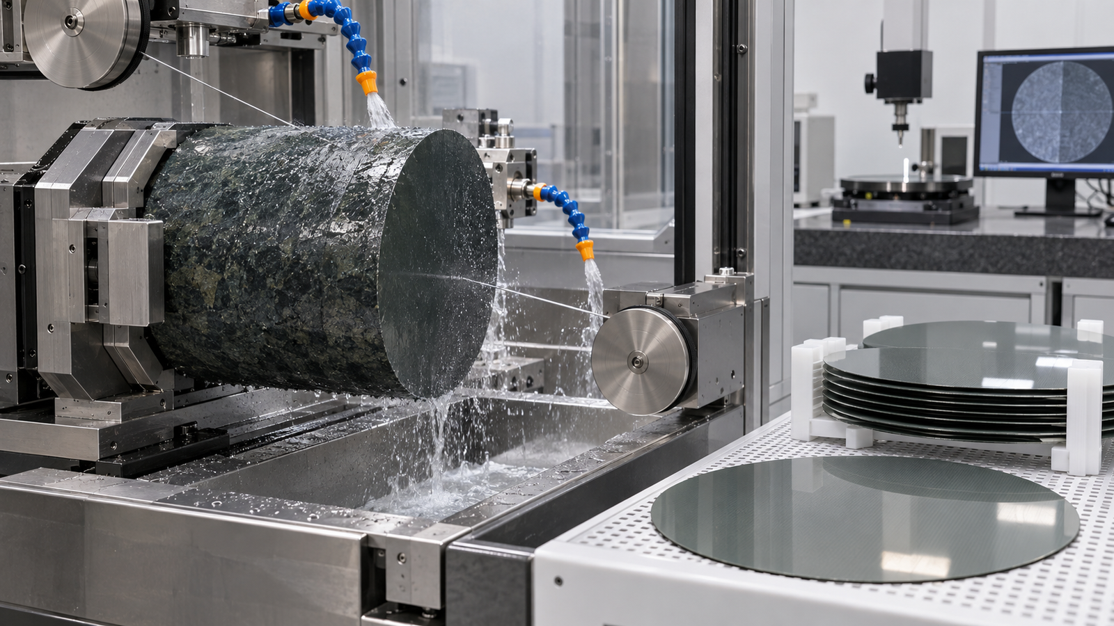
Why 300 mm SiC wafer slicing changes the cost equation
Larger wafers can place more die starts on one substrate and may improve factory compatibility. The attraction is visible in AI infrastructure, power electronics and optical applications. Yet area alone does not determine cost per accepted device. Boule yield, edge exclusion, defects, slicing loss, finishing allowance and line utilization all matter.
At the slicing step, three losses should be separated:
- Kerf loss is the material physically removed by the wire and abrasive envelope.
- Finishing allowance is the material removed later to eliminate saw marks, geometry error and subsurface damage.
- Yield loss includes wafers rejected for TTV, bow, warp, chipping, cracks or handling damage.
A narrower wire may reduce geometric kerf, but it is not automatically the lowest-cost choice. Insufficient stiffness or abrasive capacity can increase shape error and downstream removal. Optimize cost per accepted wafer, not wire diameter or cycle time alone. The SiC slicing cost model combines these losses.
What physically changes between 200 mm and 300 mm SiC
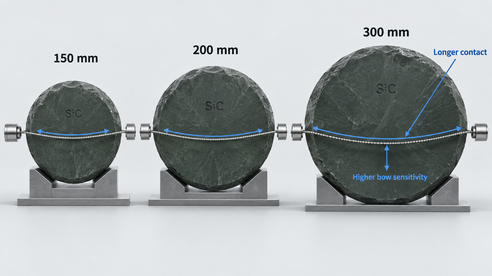
Maximum contact length increases
For the same cutting path, the wire remains engaged with a larger cross-section for longer. At entry, only a short segment cuts. Near the boule center, contact is greatest. A constant feed command therefore does not create a constant abrasive load. If feed is set for fast entry, the center region may show greater force, wire bow and temperature. If it is set conservatively for the center, the rest of the cycle may be unnecessarily slow.
Wire bow becomes more consequential
A diamond wire is flexible. Normal cutting force displaces it from the ideal straight path, while tension and guide geometry resist that displacement. More bow is not merely a machine-load issue: it changes the effective cutting path, delays feed response and can create waviness or thickness variation. On a larger wafer, a small angular or lateral deviation acts across a longer distance. Commanded tension alone is not enough; engineers should observe actual tension response, bow, motor load and wafer geometry together.
Coolant and debris face a longer path
The middle of a long kerf is the hardest place to wet, cool and clear. Used coolant, SiC debris and detached abrasive can remain in the contact zone, causing rubbing and recutting. Tank temperature and pump setting may still look normal while local conditions deteriorate. Qualification should record measured flow, inlet temperature, filter differential pressure, nozzle position and evidence of lane-to-lane or edge-to-center variation.
Fixture and machine structure carry a larger moment
Mass, overhang and bonded support geometry change with boule size. A fixture stable at 200 mm can introduce tilt or compliance at 300 mm. Beyond adequate travel, verify guide-wheel alignment, spindle behavior, workpiece support and thermal stability under actual load.
Seven outputs a 300 mm qualification must measure
A supplier trial should define the measurement method, sampling map and acceptance rule before cutting. Otherwise, each side can call the same trial successful for different reasons.
| Output | Why it matters at larger diameter | Useful qualification view |
|---|---|---|
| Kerf width | Direct raw-material consumption | Entry, center and exit; new and aged wire |
| TTV | Thickness uniformity affects downstream removal | Full-wafer map, not only five convenient points |
| Bow and warp | Global shape error grows costly over a larger area | Free-state non-contact measurement |
| Surface waviness and roughness | Reveal wire-path and abrasive engagement behavior | Profiles along and across wire direction |
| Subsurface damage | Determines grinding and polishing allowance | Validated destructive sampling on selected wafers |
| Edge chips and cracks | May propagate during handling or finishing | Defined chip-size classes and edge zones |
| Cycle stability | A good first cut does not prove production capability | Repeated runs across wire life and material lots |
Keep TTV, bow and warp separate. TTV describes thickness variation between corresponding front and back locations. Bow and warp describe wafer shape under specified support conditions. A wafer can pass one metric and fail another. The post-saw SiC metrology guide provides a practical measurement boundary and sampling approach.
How a diamond wire saw process window should be scaled
Do not transfer a 200 mm recipe by keeping every setpoint constant. Preserve the mechanism first, then tune the numbers. A useful development sequence is:
- Establish a reference cut. Use a representative crystal orientation, controlled wire condition and fully documented coolant setup. Record idle and cutting power separately.
- Map the cut by contact stage. Divide the cycle into entry, increasing contact, center, decreasing contact and exit. Compare force, bow, temperature proxy and surface location.
- Screen wire speed and feed as a pair. Higher speed can increase abrasive engagements and debris transport, but also sliding distance. Higher feed raises productive removal and grain load. One cannot be optimized without the other.
- Evaluate a variable-feed or rocking strategy. The objective is not motion for its own sake. It is a more uniform load through the contact-length cycle. Confirm that the strategy improves geometry without creating new periodic marks.
- Challenge the cooling system. Test filter loading, fluid aging, nozzle tolerance and restart conditions instead of using only fresh fluid at ideal flow.
- Repeat across wire life. A process window qualified only with new wire may disappear after abrasive blunting or pull-out begins.
Use the guide to wire speed and feed-rate development for the DOE structure, and the SiC sawing-temperature guide for thermal and coolant signals.
Endless diamond wire saw or diamond multi-wire saw?
An エンドレス・ダイヤモンドワイヤーソー and a diamond multi-wire saw answer different questions in a 300 mm program.
An endless system is useful for material characterization, orientation studies, fixture development and small-batch trials. The same loop repeatedly passes through the cut, supporting load observation, wire inspection and controlled factor changes. Its value is experimental clarity and flexibility, not replication of a production wire web.
A ダイヤモンド多線式ソー is the relevant architecture when the objective is many parallel wafers per cycle. It introduces production questions that a single-wire trial cannot answer: pitch consistency, wire-web tension distribution, guide-groove accuracy, lane-to-lane coolant delivery, wafer-position effects and simultaneous handling. A material recipe should move to multi-wire only after the main removal mechanism is understood, then be requalified for the web.
For both systems, verify that envelope, guide layout, tension range and monitoring suit the target crystal and contact length. Brochure size is not demonstrated capability.
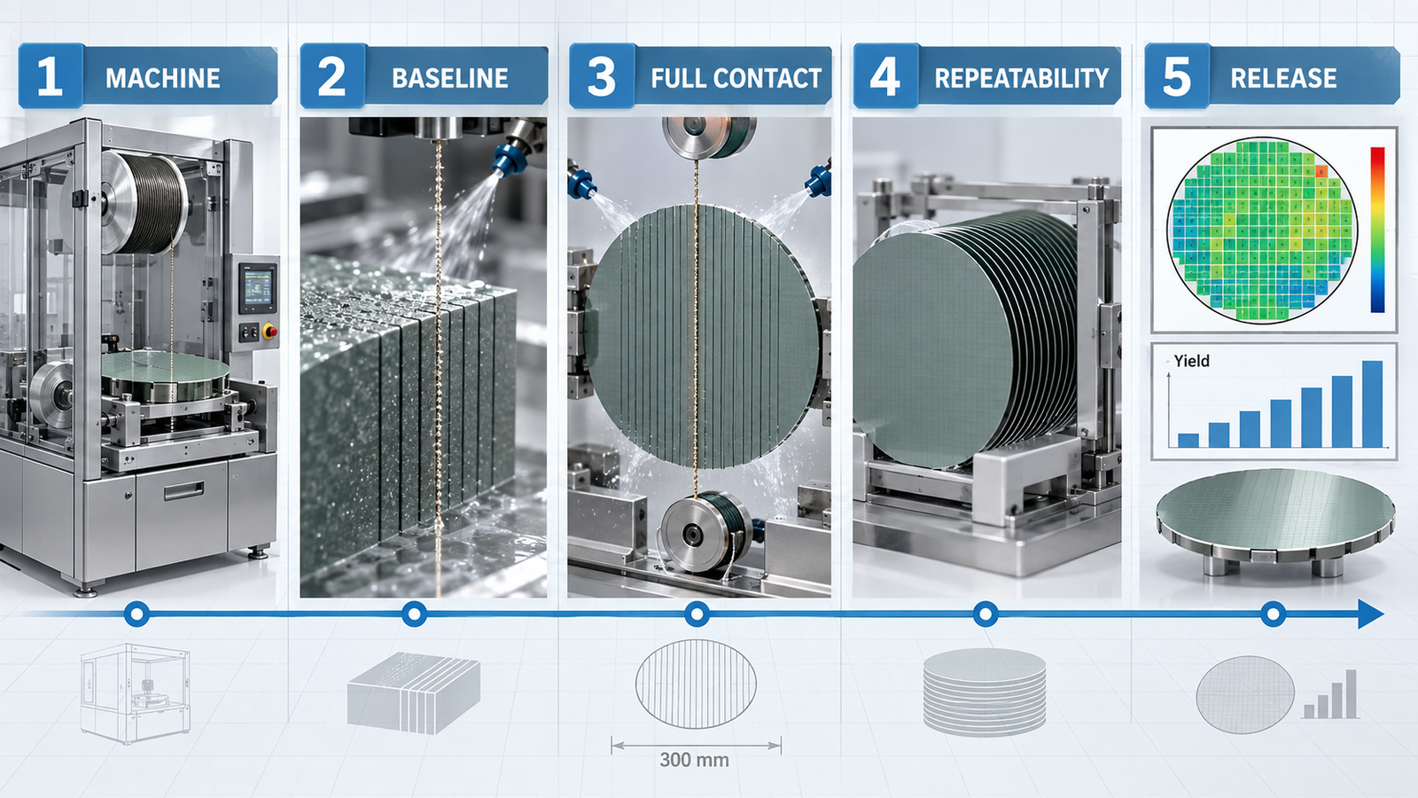
A stage-gated 300 mm SiC qualification plan
Gate 1: machine and tooling readiness
Verify workpiece envelope, loading route, fixture stiffness, wire path, guide-wheel runout, alignment method, coolant access and safe handling. Run dry or low-risk checks where appropriate before committing high-value material.
Gate 2: material-removal baseline
Cut representative coupons or shorter contact sections to establish wire specification, coolant behavior and basic force limits. Confirm that material orientation and cut direction are traceable. Do not infer full-diameter geometry from this gate.
Gate 3: full-contact engineering cuts
Use full contact length and a conservative recipe. Correlate time-series machine signals with entry-center-exit metrology. Inspect the wire at predefined intervals, not only after a failed cut.
Gate 4: repeatability and disturbance tests
Repeat cuts across operators, material lots and wire age. Introduce realistic filter loading, planned stops and restarts. The goal is to understand how the process fails and how early it can be detected.
Gate 5: capability and cost release
Calculate yield and cost using accepted wafers after the agreed finishing allowance. Report distributions and confidence intervals, not just the best wafer. Release the process only when measurement repeatability is sufficient to distinguish machine drift from metrology noise.
Procurement questions that expose hidden scale-up risk
- What target material, diameter, orientation and cut thickness has been demonstrated, and with what wire specification?
- How are wire tension, bow or cutting load monitored during the full-contact portion of the cut?
- How is coolant delivered and verified at the center of the kerf or wire web?
- Which geometric outputs were measured, with what instrument, support condition and sampling map?
- Can raw time-series data and wafer-position traceability be exported?
- How are guide wheels, fixtures and process recipes changed for larger boules?
- What evidence covers repeated cuts and aged wire rather than a single demonstration wafer?
- Who owns application support during installation, trial design and acceptance?
Write these items into the factory acceptance test. “Able to cut 300 mm” is an input statement. The purchase decision should be based on accepted output and repeatability.
How ewirexon can support a 300 mm development program
Ewirexon develops precision cutting systems for hard and brittle materials, including endless diamond wire saw platforms, diamond multi-wire saw equipment, desktop systems, consumables and auxiliary equipment. For an emerging 300 mm SiC program, the useful starting point is an application review rather than a generic machine recommendation.
That review should include boule diameter and length, orientation, target wafer thickness, finishing allowance, acceptable kerf, geometry limits, throughput objective, coolant constraints and the intended measurement plan. Ewirexon’s SiC and compound-semiconductor cutting, process-parameter consulting そして custom equipment development capabilities can then be assessed against the program gates. Where evidence is still being developed, requirements should be labeled as trial targets rather than presented as proven production specifications.
Conclusion
The 300 mm SiC milestones reported in 2025 and 2026 are strategically important, but they do not remove the hard work between a crystal demonstration and a stable wafer process. Larger diameter magnifies contact-length, wire-bow, coolant, fixture and metrology problems. A precision diamond wire saw contributes narrow kerf and controlled mechanical removal, but only a measured process window turns those advantages into accepted wafers.
For a meaningful equipment discussion, provide the actual SiC grade, crystal orientation, boule dimensions, target thickness, edge allowance, TTV and shape limits, surface-damage requirement and planned annual volume. Those inputs make it possible to choose between an endless development system, a multi-wire production architecture or a staged combination of both.
Frequently asked questions
Is 300 mm SiC already in mass production?
Public announcements show important 300 mm crystal and platform milestones, but they should not be interpreted as universal high-volume availability. Buyers should distinguish a single-crystal demonstration, pilot capability, qualified substrate supply and sustained production capacity.
Why is a 300 mm SiC wafer harder to slice than a 200 mm wafer?
The longer maximum contact length changes cutting force, wire bow, heat generation, coolant access and debris removal. Larger area also makes a local path error more expensive. The recipe, fixture, wire path and measurement plan therefore need fresh qualification.
Does a thinner diamond wire always reduce total material loss?
It reduces the geometric contribution to kerf, but total loss also includes finishing allowance and rejected wafers. If a thinner wire increases waviness, damage or breakage risk, cost per accepted wafer can rise.
Which diamond wire saw is best for 300 mm SiC?
An endless diamond wire saw is useful for R&D, orientation studies and controlled trials. A diamond multi-wire saw is needed to evaluate parallel-wafer throughput and web consistency. The right sequence depends on development maturity, material value and production target.
What data should be included in a diamond wire saw acceptance test?
Include kerf, TTV, bow, warp, waviness, roughness, chip and crack limits, subsurface-damage sampling, cycle time, wire consumption and repeated-cut yield. Define instruments, support conditions, sampling locations and material lots before the test.
Technical references
- Wolfspeed, 300 mm single-crystal SiC technology milestone, January 2026.
- Coherent, 300 mm SiC platform announcement, December 2025.
- Formation mechanism of wire bow and its influence on diamond wire saw process and wire cutting capability.
- A rocking-floating-variable speed feeding mode for slicing single-crystal silicon carbide.
Editorial note: Industry milestones are dated and linked so readers can separate announced capability from current volume production. The figures in this article are AI-generated engineering illustrations; they are conceptual and do not represent customer data, certified machine drawings or measured results.