








Glass core substrates are moving from packaging roadmaps into serious process development for large, high-density AI and high-performance computing packages. Their flatness, dimensional stability, electrical behavior, and potential for fine interconnect structures address limits that become more visible as chiplet packages grow. Intel has described glass substrates as an enabling platform for larger chiplet complexes, while current IEEE guidance links TGV fabrication, metallization, edge integrity, and mechanical reliability.
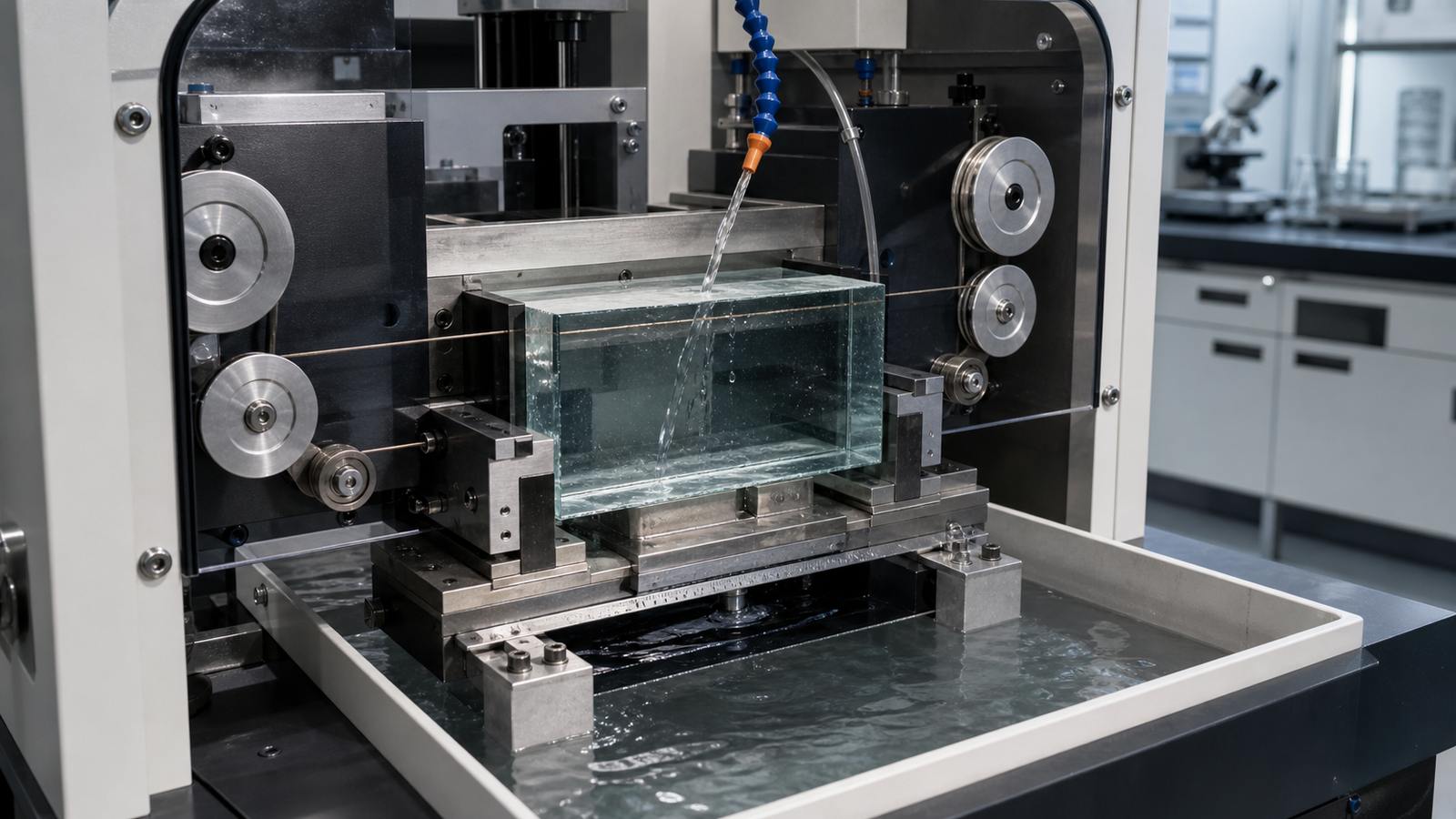
That momentum creates a practical question: where can a diamond wire saw add value? It can be a strong option for thick blanks, R&D coupons, and low-volume preforms. It is usually not the default for final singulation of a thin, metallized package panel.
A machine can make an attractive cut on an unpatterned glass block and still be unsuitable for the product flow. The useful decision is whether a diamond wire saw can meet the edge, contamination, geometry, throughput, and reliability requirements of a defined operation.
Start with the glass core substrate process stage
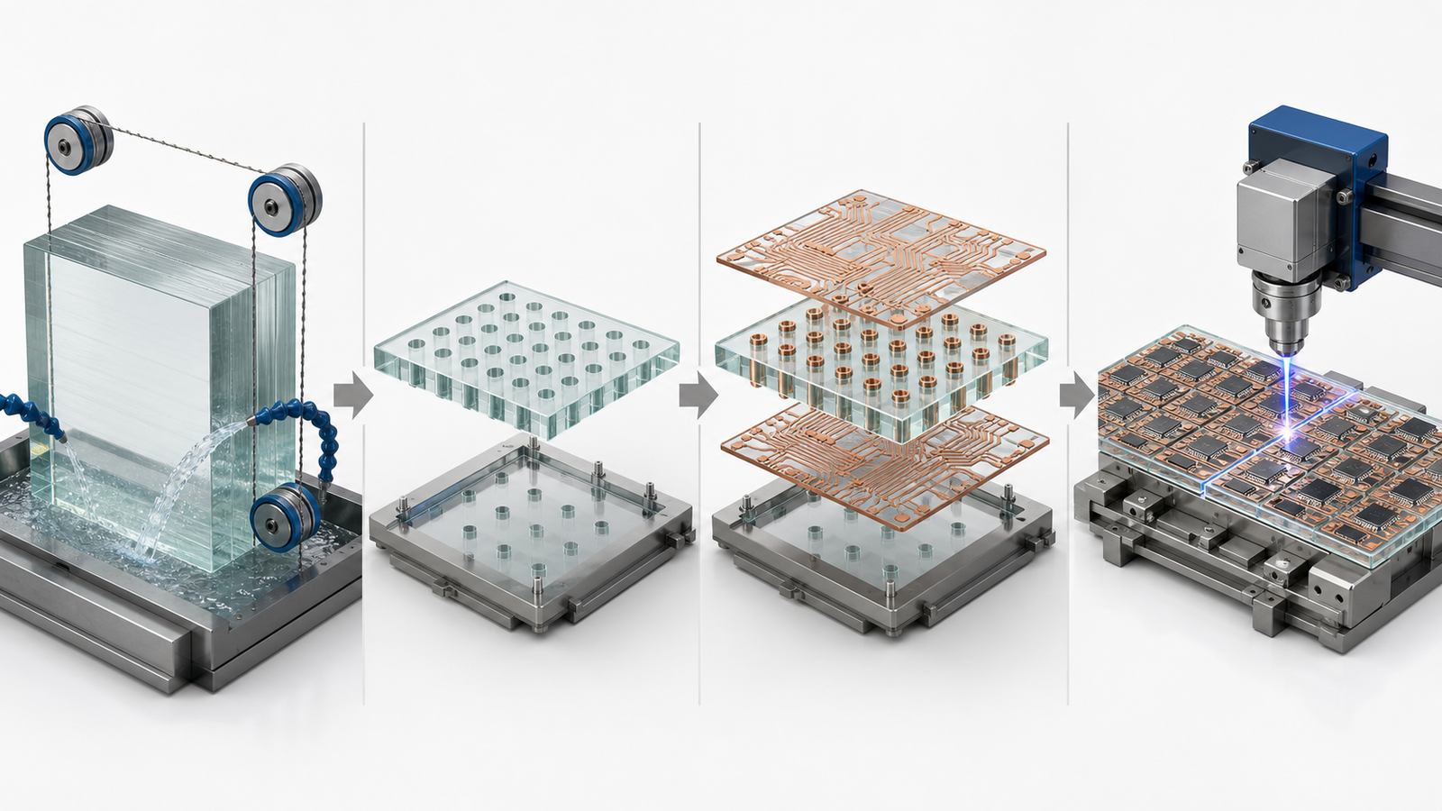
“Glass substrate cutting” can refer to operations that have little in common. Before comparing equipment, map the proposed cut to the manufacturing route.
| Process stage | Typical objective | Diamond wire saw fit |
|---|---|---|
| Thick raw glass stock or preform | Create a plate, block, or near-net blank with controlled material loss | Often worth evaluating. The flexible wire and fixed diamond abrasive can process thick brittle stock without a blade body occupying the kerf. |
| Material-development coupons | Prepare specimens for TGV, metallization, adhesion, thermal, or reliability experiments | Strong R&D use case. An endless or desktop endless loop system can support frequent geometry and material changes. |
| Thick unpatterned profiles or cavities | Remove bulk glass before fine processing | Conditional. Access, corner radius, wire path, and finishing allowance must be checked. Research has demonstrated diamond-wire-based profile cutting in quartz glass, but that does not establish a universal recipe for packaging glass. |
| TGV formation and fine redistribution features | Create microvias and electrical routing | Not a wire-saw operation. Laser modification, drilling, wet etching, plating, and lithographic processes are used at this scale. |
| Final singulation of a thin metallized panel | Separate finished units without damaging glass, copper, polymers, or active components | Usually not the first choice. Precision blade, laser-based, or other validated singulation methods may provide the feature access and throughput required. |
Thickness alone does not define the boundary. A raw blank presents a different contamination and stress problem from a panel carrying copper, dielectrics, embedded devices, or optical structures. Identify what has already been added before discussing line speed.
Why glass core cutting quality cannot be judged by appearance alone
Abrasive contact creates local tensile stress in hard, brittle glass. The visible result may be an edge chip or pit; the more serious result may be a subsurface crack that survives cleaning and grows during handling, build-up, reflow, or thermal cycling.
The 2025 IEEE Electronics Packaging Society overview on glass core substrates explains that practical glass strength is far below ideal material strength because surface microcracks concentrate stress. It also describes edge-originated cracking after build-up, singulation, or thermal cycling, including the failure mode known as SeWaRe. Its engineering implication is direct: reducing crack size at a processed edge and controlling the stress state around that edge can matter more than achieving an attractive average roughness number.
Large or thin panels add handling risk. Weight, fixture flatness, vacuum distribution, adhesive cure, and clamp pressure can impose bending before cutting. A crack blamed on the saw may begin at a fixture hard point, while a visually acceptable cut may fail later.
How a precision diamond wire saw can help upstream
A fixed-abrasive diamond wire removes glass through many small abrasive interactions along a narrow, flexible tool. In a suitable process window, this can provide four useful advantages for upstream hard brittle material cutting:
- Low tool-body interference: the wire can enter thick stock with less obstruction than a rigid blade body, which helps with deep cuts and some profiles.
- Controllable kerf: wire envelope, grit protrusion, lateral motion, and process force determine the effective kerf. A thin wire can support material conservation, but only if it tracks stably.
- No laser heat-affected zone: diamond wire sawing is mechanical, so it avoids laser thermal input. It can still create mechanical microcracks and must not be described as damage-free.
- Flexible R&D setup: an endless diamond wire saw can prepare individual coupons and accommodate low-volume work without a production dicing flow.
The continuous loop in an endless system moves in one direction through the cut, avoiding the reversal event of a reciprocating wire path. That can simplify motion behavior, but it does not eliminate wire bow, guide runout, grit wear, or fixture resonance. Stable cutting comes from the complete machine-process system, not the word “endless” in the equipment name.
Five controls that determine glass edge integrity
1. Wire envelope and abrasive condition
Effective cutting width includes the wire core, bond, diamond protrusion, runout, and lateral displacement. The smallest nominal diameter does not guarantee the lowest accepted-part cost: an undersized wire may bow, wander, or fail.
Record grit specification, bond type, wire batch, initial condition, and cumulative cut area. A conditioned wire may behave differently from a new wire, while a late-life wire may load, lose grit, or require more force. Qualification should represent the wire-life window intended for production.
2. Feed-to-wire-speed balance
Feed sets removal demand; wire speed influences how many abrasive contacts share it. Excessive feed raises force and bow, while more speed can change dynamics and wear. Trend machine load or a validated force proxy through the full contact-length range.
3. Tension, guides, and machine dynamics
Tension helps hold the intended path, but maximum tension is not the objective. Higher tension consumes wire safety margin and can increase fatigue around small guide radii. Check tension calibration, pulley alignment, groove wear, bearing condition, and no-load tracking. Periodic marks often require a frequency and mechanics investigation, not a cosmetic feed adjustment.
4. Fixture support and cut exit
Support the glass over a controlled area without locking in distortion. Document adhesive type, bond-line thickness, cure, backing plate flatness, and release method. Entry and exit deserve separate observation: first contact can initiate chips, while the last ligament can break away if the separated portion is free to rotate or sag. A sacrificial support layer or modified end-of-cut feed may improve the exit, but both need validation for the specific glass.
5. Coolant, particles, and cleanliness
Coolant must reach the abrasive contact and remove glass debris as the contact length changes. Track flow, temperature, concentration, filtration, and nozzle location. For packaging R&D, fluid residue and particles may affect later adhesion, photoresist, metallization, or electrical tests. Include cleaning and cleanliness verification in the cutting qualification rather than treating them as someone else’s process.
A qualification plan for glass substrate coupons
Begin with representative glass; composition, heat treatment, thickness, and edge history change fracture behavior. Establish a conservative baseline, then use a small designed experiment for feed-to-speed ratio, tension, wire specification, and support. Do not change all four at once.
| Output | Why it matters | Recommended evidence |
|---|---|---|
| Kerf and dimensional error | Controls blank utilization and finishing stock | Measure at multiple depths or positions; report distribution, not one value |
| Maximum edge chip | Large defects can become fracture origins | Inspect both faces, entry, exit, and corners at fixed magnification |
| Roughness and waviness | Indicate different surface-generation mechanisms | Filter and report them separately in directions relevant to the wire path |
| Subsurface damage | May survive visual inspection | Use a validated destructive cross-section, progressive polishing, or microscopy method on qualification samples |
| Residual stress / birefringence | Can reveal handling or process-induced stress patterns | Use a repeatable polarized-light method with an agreed reference state |
| Cleanliness and downstream compatibility | Particles or residue can disrupt later processing | Define cleaning, particle, surface-energy, or adhesion checks appropriate to the next step |
| Repeatability and wire life | One good coupon does not establish capability | Repeat across material locations, operators, and a meaningful portion of wire life |
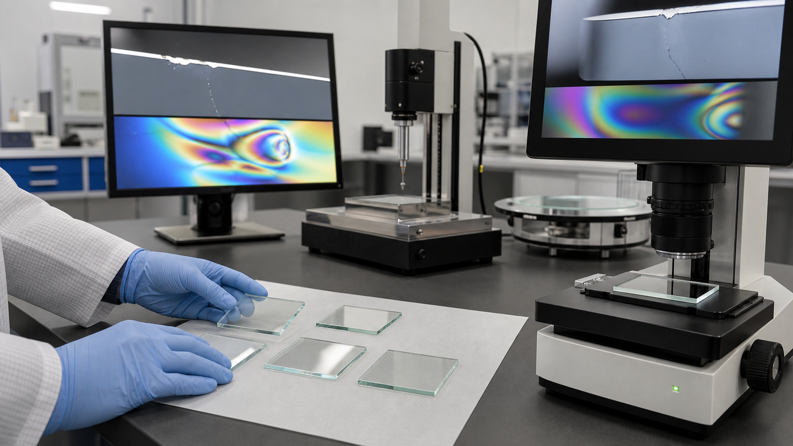
Diamond wire saw, blade, or laser: make a stage-specific choice
| Method | Potential strength | Important limitation |
|---|---|---|
| Endlos-Diamantdrahtsäge | Thick blanks, coupons, deep cuts, flexible profiles, low-volume material development | Mechanical edge and subsurface damage remain possible; minimum radius and productivity depend on wire path and machine dynamics |
| Diamant-Mehrdrahtsäge | Parallel slicing of suitable upstream glass stock when repeated plates are required | Process and thickness stack must be stable before scaling; it is not a substitute for fine-feature dicing |
| Precision dicing blade | Established straight-line singulation, thin kerf options, mature handling ecosystems | Blade loading, chipping, coolant interaction, and stress at multilayer edges require optimization |
| Ultrafast laser or laser-modification process | Fine access, non-contact energy delivery, and potential for high-speed panel patterns | Capital cost, material-specific absorption, modified zones, debris, edge strength, and multilayer interactions must be qualified |
Compare accepted parts per hour, edge strength after relevant thermal exposure, cleaning, finishing stock, consumables, and yield at the intended geometry. A demonstration on another glass composition is feasibility evidence, not a production guarantee.
Choosing endless, desktop, or multi-wire equipment
A desktop endless loop diamond wire saw suits material screening, small coupons, and low-volume development when its envelope and tension range fit. Larger endless systems support thicker blanks and longer cuts. A diamond multi-wire saw belongs in repeated upstream slicing only after thickness, bow, coolant distribution, and edge quality are stable.
Equipment requests should include glass composition or grade, stock dimensions, target blank geometry, finishing allowance, maximum chip size, flatness target, cut-face requirement, downstream process, cleanliness restrictions, and volume. Ewirexon’s application pages for thin glass profile cutting, brittle electronic plate machining, and quartz and optical glass slicing show the broader material scope. Its process parameter consulting and custom equipment development pages are more relevant when the fixture, path, or cleaning boundary is non-standard.
The useful supplier conversation starts with samples and acceptance evidence, not a claim of micron accuracy detached from workpiece size and measurement method.
Conclusion
Advanced packaging is making glass core substrates and their edge integrity more consequential. A small crack created early can become a yield or reliability problem after TGV formation, metallization, build-up, and assembly add value.
A precision diamond wire saw can be valuable for upstream blank preparation, R&D coupons, and selected thick-glass profiles. Its advantages are strongest when the process needs flexible geometry, controlled kerf, and mechanical cutting without laser heat input. Its limits are equally important: it does not create microvias, and it is not automatically the right final singulation method for a thin, functional package panel.
For a meaningful cutting trial, provide the actual glass grade, dimensions, target geometry, edge criteria, downstream process, cleanliness rules, and expected volume. That information allows an endless, desktop, multi-wire, blade, or laser approach to be compared against the real manufacturing objective.
FAQ
Can a diamond wire saw cut glass core substrates?
Yes, a diamond wire saw can cut many glass materials, but the useful application must be defined. It is most credible for thick blanks, preforms, R&D coupons, and selected profiles. Final singulation of thin metallized glass core panels may be better served by a qualified blade or laser-based process.
Does diamond wire sawing eliminate microcracks in glass?
No. It avoids a laser heat-affected zone, but it is still a mechanical abrasive process. Wire grit, force, vibration, fixturing, and cut exit can create edge or subsurface cracks. Qualification should include more than visual inspection and average roughness.
What is the main benefit of an endless diamond wire saw in R&D?
An endless diamond wire saw supports controlled single cuts, flexible coupon sizes, and frequent material changes. Continuous one-direction wire motion can simplify process development, although guide condition, tension, bow, and wear still need monitoring.
When would a diamond multi-wire saw be appropriate for glass?
A diamond multi-wire saw may be appropriate when upstream glass stock must be sliced into many parallel plates with repeatable spacing. It should be evaluated after the single-cut process, coolant distribution, thickness tolerance, and edge criteria have been demonstrated. It is not intended for forming TGVs or fine package features.
What information should be sent for a glass cutting trial?
Send the glass composition or supplier grade, stock size, target geometry, finishing allowance, maximum edge-chip limit, flatness or thickness tolerance, cut-face requirement, downstream process, cleaning restrictions, and expected production volume. Include representative material whenever possible.
Technical sources
- Intel Newsroom: glass substrates for next-generation advanced packaging
- IEEE Electronics Packaging Society: Glass Core Substrate technical overview (2025)
- Advanced Glass Substrate Fabrication and Metallization Process Technology for Co-Packaged Optics (ECTC 2025)
- Shape-cutting of quartz glass by spark discharge-assisted diamond wire sawing
Editorial note: This article was developed with AI-assisted research and English editing. Technical statements were checked against the cited primary sources and Ewirexon’s published application information. The illustrations are AI-generated conceptual visuals, not customer process photographs or measured test results. Process values and method selection must be validated with representative material.