
Glass is moving deeper into advanced semiconductor packaging as a carrier, panel, core-substrate candidate and precision process material. Its dimensional stability, smooth surfaces, electrical insulation and potential for large formats are attractive. Its edge, however, remains a manufacturing liability: one small chip or subsurface crack can grow during debonding, metallization, thermal cycling or panel handling.
Industry work in 2026 reflects the shift. SEMI and Global Net released a report focused on glass-core substrate markets and development trends. Corning emphasizes ultra-flat glass carriers and edge strength, while suppliers continue to develop wet metallization and through-glass integration processes. Cutting is only one step in that ecosystem, but it establishes the edge condition inherited by every later step.
A Diamantdrahtsäge can separate thick glass plates, carrier blanks, development panels and coupons with low force and a narrow kerf. It is not a replacement for panel dicing, laser via formation or final edge finishing. This guide defines where wire cutting fits and how to qualify edge strength instead of accepting a visually intact part.
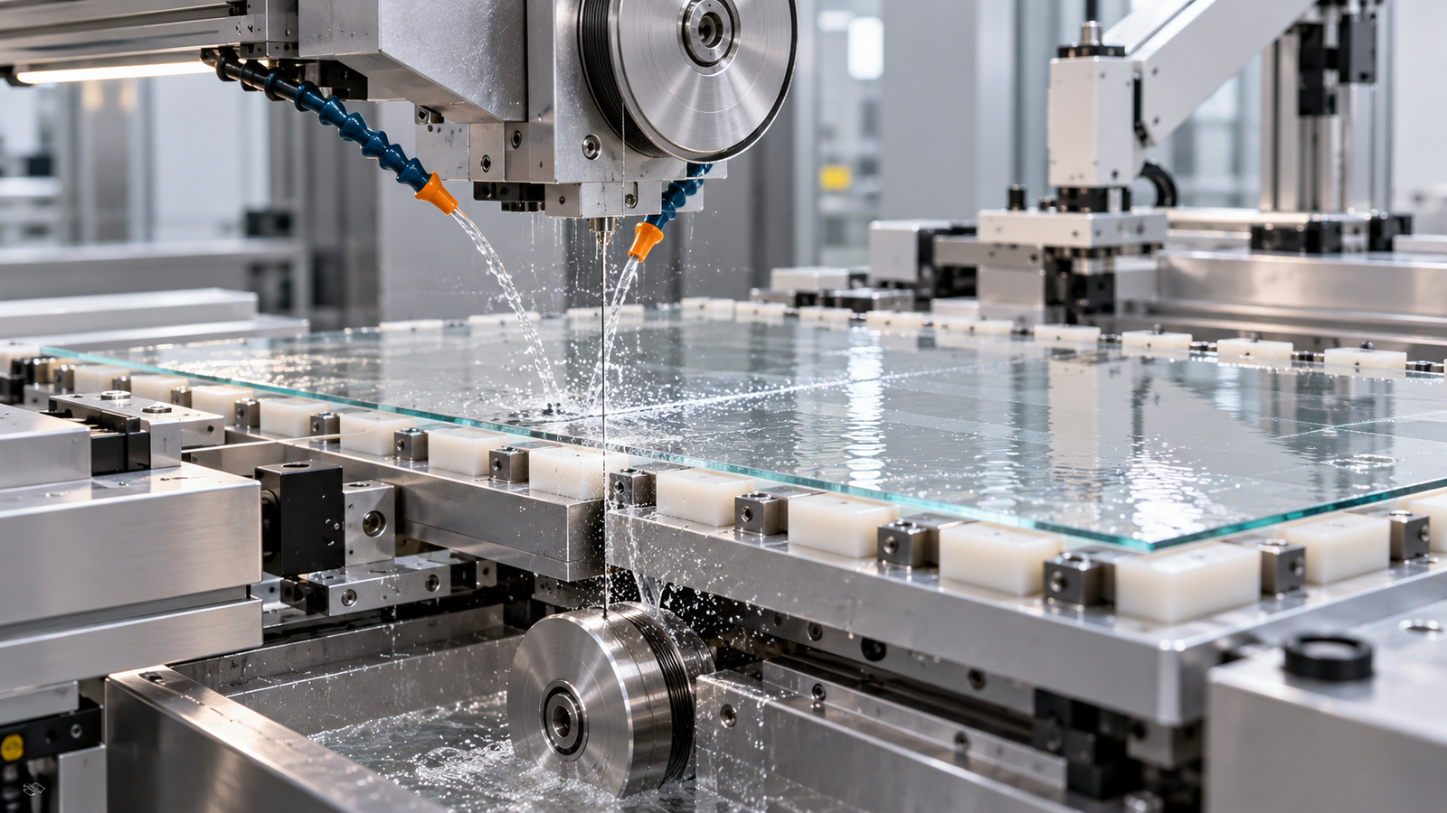
Why advanced packaging puts more stress on glass edges
Packaging glass can experience temporary bonding, coating, lithography, laser processing, metallization, plating, cleaning, thermal excursions and robotic handling. Large panels amplify small flatness and stress errors. Thin glass reduces mass and package height but becomes more sensitive to support and local contact.
The edge may serve several functions: a handling datum, a clamp zone, a reference for alignment or simply the boundary that must survive the process. Defects outside the electrical area still matter if they lower panel strength. Specify an edge exclusion zone and distinguish cosmetic defects from strength-critical cracks.
Glass composition, thickness, ion exchange, annealing, coatings and residual stress all change fracture behavior. “0.5 mm glass” is not a complete material specification. Record the exact grade, lot and prior process history before comparing cutting results.
Visible chips are only part of the risk
Brittle removal creates surface chips and a subsurface crack network. A bright-field image may show a clean edge while cracks extend below it. Those cracks can grow under bending, thermal mismatch or chemical attack. Edge strength is statistical because failure begins at the most severe flaw within the loaded region.
Useful outputs include:
- maximum and cumulative chip dimensions by edge segment;
- edge profile, taper and local thickness loss;
- directional roughness and waviness on cut faces;
- subsurface-damage depth from a validated sampling method;
- strength distribution after the intended finishing and cleaning route;
- breakage during unloading, transport and downstream simulation.
A single bend-strength average is inadequate. Report specimen count, edge preparation, loading direction and distribution. The weakest tail often controls manufacturing yield.
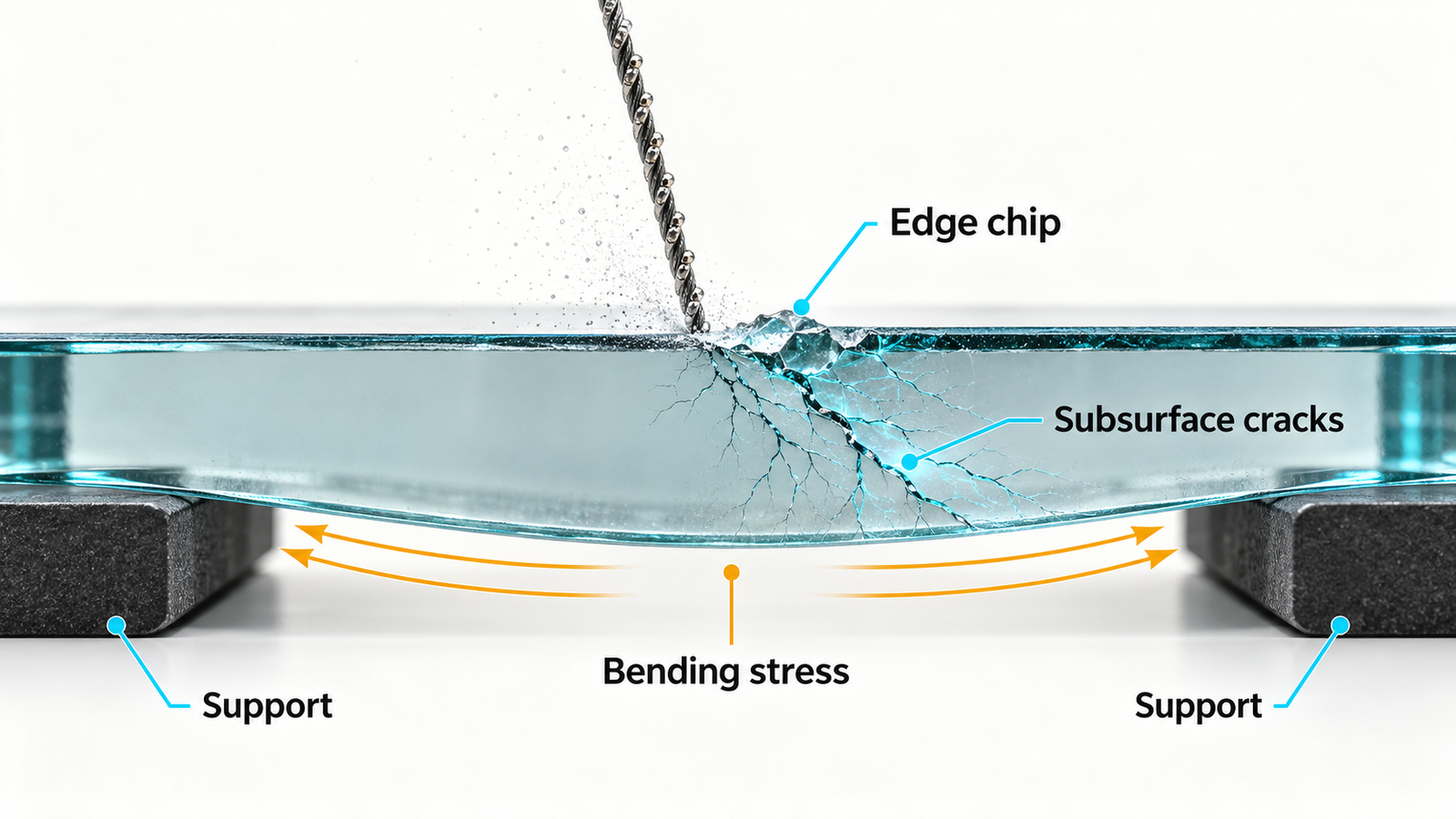
How diamond wire cutting can protect the edge
A fixed-abrasive diamond wire spreads material removal over many small contacts. With stable tension, suitable abrasive and effective debris removal, cutting force can remain lower than with broad rigid tools. Narrow kerf also preserves valuable panel area. The advantages disappear when the wire vibrates, loads with glass debris or exits an unsupported edge.
Match wire to thickness and finishing route
Fine wire and fine abrasive can reduce geometric kerf and the scale of individual scratches, but lower stiffness increases sensitivity to bow and vibration. Choose the combination that minimizes cut kerf plus edge-trim and finishing stock, not the wire with the smallest catalog diameter.
Control grain load with feed and speed
Feed rate, wire speed and contact length establish the average load on active grains. Thin glass often needs a conservative entry and exit profile. If the machine maintains constant feed while engagement changes, the edge can see a large transient. Monitor drive load, tension response and cut position during trial development.
Keep debris moving out of the kerf
Glass particles trapped in the kerf can be pressed into the surface or recut into larger chips. Coolant delivery should reach both sides without creating a jet that moves the wire or panel. Trend filtration and temperature, and inspect nozzles after any broken part.
Support the panel throughout cutting and unloading
Thin glass should not be considered free-standing just because the machine can clamp one edge. Full-area support, bonded sacrificial plates or vacuum fixtures may distribute load, but each method introduces risks. Adhesive can shrink, create hard spots or leave residue; vacuum features can print through or concentrate stress; backing materials can change exit behavior.
Run a support comparison with identical glass and wire conditions. Inspect the full perimeter and record breakage after fixture release. A panel that passes on the machine and fails during adhesive removal has not passed the cutting process.
Design unloading before buying the machine. Define gripper contact, tray flatness, separator films, maximum manual handling and the allowed panel deflection. For large formats, handling automation may affect yield more than a small difference in cutting speed.
Separate residual stress from cutting damage
Incoming glass may contain residual stress from forming, tempering, ion exchange, coating or bonding. Use appropriate stress inspection before cutting. If failures cluster without a clear wire-direction signature, compare stress maps and lot history.
Cutting can also introduce local heating and mechanical stress. Monitor coolant temperature and avoid dry intervals. If a crack follows a coating edge or bonded interface, investigate thermal-expansion mismatch and adhesion rather than tuning only the wire.
A recent experimental study on thin-glass cutting highlights the importance of suppressing crack initiation and propagation. While the method may differ from diamond wire sawing, the central engineering lesson transfers: crack control is an edge-system problem involving load, support and material state.

A qualification flow for advanced packaging glass
- Define the real stack. List glass grade, thickness, coatings, bonded layers, edge exclusion and stress history.
- Establish incoming inspection. Measure dimensions, flatness, edge condition and residual stress where relevant.
- Screen support concepts. Compare backing, adhesive or vacuum approaches and include release.
- Develop the cutting window. Vary wire, feed, speed, tension and coolant one factor at a time around a stable baseline.
- Map edge defects. Preserve entry, exit, wire direction and panel coordinates.
- Apply the planned finishing. Do not compare as-cut parts if production will grind, polish or chemically treat the edge.
- Test strength and handling. Use representative loading, cleaning, debond and thermal conditions.
- Run repeated panels. Include later wire-life stages and normal operator changeover.
Where endless and multi-wire saws fit
Ein endless diamond wire saw for thin glass is useful for development plates, coupons, small batches and special profiles when the glass can be adequately supported. It gives engineers access to vary fixture and entry angle. A desktop system can prepare laboratory coupons without dedicating a large production machine.
A diamond multi-wire saw can produce parallel strips or plates when pitch and unloading are standardized. It should be qualified across the full web because outer lanes may receive different support or coolant. Multi-wire equipment is not automatically suitable for large finished panels; wire access, panel support and downstream dimensions determine the fit.
Laser separation, scribing, grinding and dicing may be better choices for thin finished panels or fine package singulation. Use diamond wire cutting where thick blanks, narrow kerf, low force and flexible material preparation create value. A process supplier should define that boundary clearly.
Procurement requirements for edge-strength control
| Topic | Evidence to request |
|---|---|
| Material fit | Trials on the actual glass grade, thickness and coating state |
| Fixture | Support drawing, release procedure and panel-deflection limit |
| Process data | Feed, speed, tension/load, coolant and cut-position logs |
| Edge quality | Chip map, inspection method, SSD evidence and finishing allowance |
| Strength | Defined test geometry, sample count and failure distribution |
| Capacity | Accepted panels per shift including loading, release and cleaning |
Ask the supplier to retain failed panels in the report. Excluding breakage produces an attractive surface-quality summary and a misleading yield estimate.
How ewirexon supports thin-glass development
Ewirexon develops endless diamond wire saw and diamond multi-wire saw equipment for glass, quartz, silicon, SiC, sapphire and ceramic applications. Its relevant experience includes glass-core substrate R&D and precision base-material cutting.
For an advanced-packaging glass project, the starting package should include the material datasheet, full stack, dimensions, required edge exclusion, surface and strength targets, planned finishing, handling flow and output. A controlled sample trial can then determine whether wire cutting belongs at blank preparation, coupon development or repeated plate production.
Fazit
Advanced packaging increases the value of glass and the consequences of a weak edge. Diamond wire saw cutting can prepare glass blanks and development parts with low force and narrow kerf, but visual inspection alone cannot qualify the process.
Preserve edge coordinates, measure subsurface damage, include support release and test the real downstream sequence. Equipment selection should be based on accepted panels and edge-strength distribution, not a photograph of one intact cut. That discipline turns thin-glass cutting from a separation step into a controlled input to packaging yield.
Häufig gestellte Fragen
Can a diamond wire saw cut thin glass for advanced packaging?
It can prepare supported plates, blanks, strips and R&D coupons. Suitability depends on thickness, size, support, final geometry and whether another process is better for fine singulation.
Why does edge strength matter in packaging glass?
Cracks at the edge can grow during handling, debonding, metallization and thermal cycling. One severe flaw can determine failure even when the surface looks acceptable.
How can edge chipping be reduced?
Use stable fine-abrasive cutting, controlled entry and exit feed, full support, effective debris removal and a qualified release method. Verify the result after finishing.
Does lower kerf guarantee higher glass yield?
No. Fine wire that bows or vibrates may create deeper damage and more edge trimming. Calculate total loss through the accepted panel.
What should a thin-glass cutting trial measure?
Measure kerf, geometry, chips, directional roughness, subsurface damage, strength distribution and breakage through unloading and downstream simulation.
Technische Hinweise
- SEMI and Global Net glass-core substrate market and development report, 2026.
- Corning advanced-packaging glass carriers and edge-strength considerations.
- Experimental research on crack suppression in thin-glass cutting.
- MKS Atotech glass-substrate metallization process, 2026.
Editorial note: Glass strength is statistical and application-specific. The figures are AI-generated engineering illustrations, not customer installations or certified package drawings.